1976 - Marshall 2203 - JMP - Restoration

IANM

New Member
Joined
Jan 3, 2022
Messages
11
Reaction score
14
Hello,
I've recently acquired an old 76' JMP from a local rocker.
He used this amp in a live setting over the course of a decade or so.

It appears the amp has been sitting in poor storage for the last decade or two and I've been cleaning up the chassis and cab.

I've just started to look at the circuit and see a few changes that I wouldn't mind getting a second opinion on.
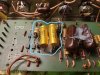
Photo 1-2
The original capacitors were changed with these massive brown ones.
Question: They're unmarked, anyone have any idea what these are??
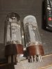
Photo 3
Looks like a normal Sprague replacement, will compare against a schematic.
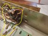
Photos 4-5
Looks like there is some crazy resistor magic going on here to add up to a specific value, anyone knows what this would be used for?
Should I replace this with a correct value rather than running them in series together?
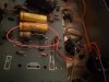
Photo 6
Another unmarked brown capacitor run across the middle pot.

Does anyone know what value this cap is and the benefits of adding this across the middle pot?

Photo 7
Looks like there was a resistor added across a pot then removed but left in place.

Does anyone know the benefit here or why this would have been added?

Photo 8
Looks like a resistor was added then removed?
Does anyone know what's going on here?

Photo 9
I am not exactly sure what this is going on without pulling the board.
Can anyone provide me with some insight so I don't need to pull the board?

Thanks so much in advance for any help.
 

Attachments

  • Capacitor Change - Brown - 2.jpg
    Capacitor Change - Brown - 2.jpg
    284.5 KB · Views: 93
  • Capacitor Change - Brown.jpg
    Capacitor Change - Brown.jpg
    287.2 KB · Views: 83
  • Capacitor Change - Sprague.jpg
    Capacitor Change - Sprague.jpg
    298.4 KB · Views: 75
  • Input - Resistor Magic - 2.jpg
    Input - Resistor Magic - 2.jpg
    245.3 KB · Views: 79
  • Input - Resistor Magic.jpg
    Input - Resistor Magic.jpg
    270.9 KB · Views: 75
  • Middle Potentiometer - Capacitor .jpg
    Middle Potentiometer - Capacitor .jpg
    254.4 KB · Views: 78
  • Potentiometer- Resistor Magic.jpg
    Potentiometer- Resistor Magic.jpg
    279 KB · Views: 74
  • WTF.jpg
    WTF.jpg
    288.7 KB · Views: 83
  • Resistor Change.jpg
    Resistor Change.jpg
    304.9 KB · Views: 81

South Park

Well-Known Member
Joined
Sep 14, 2019
Messages
4,045
Reaction score
3,938
The big brown caps are coupler caps coming off the phase inverter. The s Prague caps are for the bias stock specs are 10uf 47uf is over built .the input looks like some gain mod less signal going to the pot .resister on the pot no need .WTF a bad wire end. Last one a bias range resister . You have some tone shaping on with those pots and caps . The stuff on the pots and jacks can be removed . The parts on the circuit board are to big for that board but it works
 

VERVEHAMMER

Well-Known Member
Joined
Jun 18, 2021
Messages
183
Reaction score
307
Congratulations!
Is it Stand Up or Lay Down mains transformer?
6550's or el34's?. Small logo/Medium Logo?
I am constantly impressed at the wealth of knowledge at this forum.
 
Last edited:

Matthews Guitars

Well-Known Member
Joined
Aug 17, 2019
Messages
8,799
Reaction score
15,095
Being a 2203 it won't have a laydown mains transformer. That particular choice applies to 1959s and 1987s but I've never seen or heard of a 2203 or 2204 with a laydown mains transformer.

Looks like your amp needs maybe 2 hours of labor to get it back to fully stock condition with all correct parts, plus a new set of filter caps are probably in order. (Maybe not, but at this point, any originals are surely near the end of life if not on borrowed time.)

You didn't show front, back, and overall top and bottom photos to show the general condition.

Being a '76 with rocker switches, it'd have to be a pretty early example with rockers. As I recall, '76 was a transitional year,
with some having toggle switches and others rockers. It should have cascaded gain stages.

If the front and back gold panels are in poor condition, I have replacements for both.
 

VERVEHAMMER

Well-Known Member
Joined
Jun 18, 2021
Messages
183
Reaction score
307
1976 = Serial number code H, (Now, I ain't claiming to be special)
I have 2 USA Imports small logo 76's Stand up Mains metal switches and circle indicator lights, and 2 Canadian Lay down mains 76's, medium logo el34's, Black Dog ear switches and red cube indicator lights. Around 500 plate volts. Ei big bottle 6ca7's in one of them. Yes, the lay downs mains transformer amps sound fantastic.
They even made JCM 800's with metal toggle switches for Canada. Canada has/had different safety regs, they added a extra fuse panel inside chassis, also.

He's right.
Absolutely Recommend Cap Job. Filter caps and Bias Supply.
"In for a penny, in for a pound."
You'll never know how good it can sound without fresh Filter Caps.
 
Last edited:

VERVEHAMMER

Well-Known Member
Joined
Jun 18, 2021
Messages
183
Reaction score
307
I forgot to say, Welcome to the Forum!:welcome:
You have a great amp!
The more information/pictures posted the more Forum members have the ability to add helpful information regarding your rare, (IMHO), 1976 2203. In my small world, I've never seen a 1975 2203, besides the Marshall Book. There has to still be some out there, somewhere.
 
Last edited:

Spanngitter

Well-Known Member
Joined
Jan 22, 2019
Messages
515
Reaction score
563
Location
Upper Palatinate / Bavaria
These mods are fairly old or done by someone who had a larger stock of US origin NOS parts (Brown drops, ERIE Series 9 Resistors)
Bias caps are replaced with fairly (too) big one's, same for the coupling caps (0.1 or 0.047uF instead of 0.022uF) and it seems like it was converted to gain staging.
It would take approx 2-3h Benchtime and a hand full of parts ( Filter and Bias Caps, Coupling caps, a few resistors) to revert that unit back to stock as shipped in 1976...
 

neikeel

Well-Known Member
Joined
Feb 12, 2014
Messages
8,452
Reaction score
9,603
I agree with the others. I get quite a few amps in this condition and they rarely sound good (I presume that you have not played it!

The mods were done in a lazy way (those big carbon comp Erie resistors will likely measure way over spec (they were +/- 10% when new!).

The 220k that it half on half off was probably used to tap off some gain (shunt from pot to ground). The 100k are probably to make the lo input more lively.

I would do as suggested, carefully desolder those 100k resistors, the 220k, the extra cap on the pot, big output couplers and bias caps. The tacked on bias diode and resistor.

The burned orange wire can be saved by cutting the manky end off ad desoldering then pulling the old wire through and remaking the connection through the board.

Then decide what you are going to do with it:
-either way a set of 50/50uF 500v F&T can caps and Piher 0.5w bias dropper resistor and a 1N4007 bias diode and 10uF 200v F&T bias caps. Consider x4 new 1k 5w screen resistors and fresh set of tubes.

- stock 0.022uF 400v output couplers (buff coloured ITT match the others) and EL34s (27k bias feed resistor).

- tweaked 0.1uF 400v output couplers for 6550s (15k bias feed resistor) and add a 1500pF cap over the 470k on the input jacks (actually makes use of the extended low end that the 0.1uF couplers gives you).

Either way it is 2 hours of bench time and £200 (or equivalent) in parts for tubes and caps.
 

IANM

New Member
Joined
Jan 3, 2022
Messages
11
Reaction score
14
I agree with the others. I get quite a few amps in this condition and they rarely sound good (I presume that you have not played it!

The mods were done in a lazy way (those big carbon comp Erie resistors will likely measure way over spec (they were +/- 10% when new!).

The 220k that it half on half off was probably used to tap off some gain (shunt from pot to ground). The 100k are probably to make the lo input more lively.

I would do as suggested, carefully desolder those 100k resistors, the 220k, the extra cap on the pot, big output couplers and bias caps. The tacked on bias diode and resistor.

The burned orange wire can be saved by cutting the manky end off ad desoldering then pulling the old wire through and remaking the connection through the board.

Then decide what you are going to do with it:
-either way a set of 50/50uF 500v F&T can caps and Piher 0.5w bias dropper resistor and a 1N4007 bias diode and 10uF 200v F&T bias caps. Consider x4 new 1k 5w screen resistors and fresh set of tubes.

- stock 0.022uF 400v output couplers (buff coloured ITT match the others) and EL34s (27k bias feed resistor).

- tweaked 0.1uF 400v output couplers for 6550s (15k bias feed resistor) and add a 1500pF cap over the 470k on the input jacks (actually makes use of the extended low end that the 0.1uF couplers gives you).

Either way it is 2 hours of bench time and £200 (or equivalent) in parts for tubes and caps.

Thank you so much for the detailed notes, I am going to follow your instructions here, was just recovering from a busy work week and booster shot....

I will carefully desolder the resistors and cap on the pots, massive output couplers and bias caps.
(I am new to amp repair but committed to learning and restoring this) I assume the bias diode and resistor are, these should also be removed (see photo)?
I will un-attach the manky orange wire and re-attach, this seems straightforward.

I am about to put an order for a set of 50/50uF 500v F&T filter caps to ensure a smooth DC current throughout the amp, and a set of 10uF 200v F&T bias caps to replace the current spragues in place. I will also buy a set of new screen resistors.

I am going to run it with EL34's so will buy some 0.022uF 400v coupler capacitors. The site in which I was planning to buy parts off of only has these two options for .0022uF 400v caps, will either of these suffice (see attached).

Questions -
I am not familiar with .5 bias dropper resistor and a 1NA4007 bias diode, can you explain to me where I will put these?
The amp came with these old Tesla EL34's, 3/4 of them appeared pretty clean with 1 that is broken and has a crack, should I go to my local tube shop and see these still have life in them and to see if they can find me a 4th matched tube or should I just order something like Mullard reissues?


Thanks again in advanced.
 

Attachments

  • Bias Diode + Resistor.jpg
    Bias Diode + Resistor.jpg
    143.4 KB · Views: 18
  • Tubes.jpg
    Tubes.jpg
    244.7 KB · Views: 17
  • Caps.jpg
    Caps.jpg
    74.1 KB · Views: 17
Last edited:

neikeel

Well-Known Member
Joined
Feb 12, 2014
Messages
8,452
Reaction score
9,603
Thank you so much for the detailed notes, I am going to follow your instructions here, was just recovering from a busy work week and booster shot....

I will carefully desolder the resistors and cap on the pots, massive output couplers and bias caps.
(I am new to amp repair but committed to learning and restoring this) I assume the bias diode and resistor are, these should also be removed (see photo)?
I will un-attach the manky orange wire and re-attach, this seems straightforward.

I am about to put an order for a set of 50/50uF 500v F&T filter caps to ensure a smooth DC current throughout the amp, and a set of 10uF 200v F&T bias caps to replace the current spragues in place. I will also buy a set of new screen resistors.

I am going to run it with EL34's so will buy some .0022uF 400v coupler capacitors. The site in which I was planning to buy parts off of only has these two options for .0022uF 400v caps, will either of these suffice (see attached).

Questions -
I am not familiar with .5 bias dropper resistor and a 1NA4007 bias diode, can you explain to me where I will put these?
The amp came with these old Tesla EL34's, 3/4 of them appeared pretty clean with 1 that is broken and has a crack, should I go to my local tube shop and see these still have life in them and to see if they can find me a 4th matched tube or should I just order something like Mullard reissues?

Thanks again in advanced.

I'll send reply tomorrow
 

IANM

New Member
Joined
Jan 3, 2022
Messages
11
Reaction score
14
Being a 2203 it won't have a laydown mains transformer. That particular choice applies to 1959s and 1987s but I've never seen or heard of a 2203 or 2204 with a laydown mains transformer.

Looks like your amp needs maybe 2 hours of labor to get it back to fully stock condition with all correct parts, plus a new set of filter caps are probably in order. (Maybe not, but at this point, any originals are surely near the end of life if not on borrowed time.)

You didn't show front, back, and overall top and bottom photos to show the general condition.

Being a '76 with rocker switches, it'd have to be a pretty early example with rockers. As I recall, '76 was a transitional year,
with some having toggle switches and others rockers. It should have cascaded gain stages.

If the front and back gold panels are in poor condition, I have replacements for both.
I'd be very interested in front and back panels if you have extra.
Send me a message if you are able to.
 

Chris-in-LA

Well-Known Member
Joined
Jul 19, 2018
Messages
3,862
Reaction score
4,188
Location
Los Angeles
Thank you so much for the detailed notes, I am going to follow your instructions here, was just recovering from a busy work week and booster shot....

I will carefully desolder the resistors and cap on the pots, massive output couplers and bias caps.
(I am new to amp repair but committed to learning and restoring this) I assume the bias diode and resistor are, these should also be removed (see photo)?
I will un-attach the manky orange wire and re-attach, this seems straightforward.

I am about to put an order for a set of 50/50uF 500v F&T filter caps to ensure a smooth DC current throughout the amp, and a set of 10uF 200v F&T bias caps to replace the current spragues in place. I will also buy a set of new screen resistors.

I am going to run it with EL34's so will buy some .0022uF 400v coupler capacitors. The site in which I was planning to buy parts off of only has these two options for .0022uF 400v caps, will either of these suffice (see attached).

Questions -
I am not familiar with .5 bias dropper resistor and a 1NA4007 bias diode, can you explain to me where I will put these?
The amp came with these old Tesla EL34's, 3/4 of them appeared pretty clean with 1 that is broken and has a crack, should I go to my local tube shop and see these still have life in them and to see if they can find me a 4th matched tube or should I just order something like Mullard reissues?


Thanks again in advanced.
I’ve used the orange drop and the yellow types before but I think you need .022, not .0022.
 

IANM

New Member
Joined
Jan 3, 2022
Messages
11
Reaction score
14
I’ve used the orange drop and the yellow types before but I think you need .022, not .0022.
Great catch, I have .022 uF in the cart but made a typo in the response.
It certainly made me double-check, and thanks for confirming the orange drops should be fine =D.
 
Top