AVT 150 blown output

  • Thread starter unicorna
  • Start date
  • This site may earn a commission from merchant affiliate links like Ebay, Amazon, and others.

unicorna

New Member
Joined
Sep 11, 2013
Messages
15
Reaction score
17
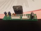
I bought an AVT 150 with blown output. Pre-amp stage works perfectly. Anyway removed the chassis and checked the output boards and one had obvious signs of being blown.
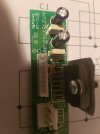
Removed both output boards and replaced both amp chips.
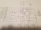
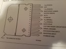
Question: were there variations in the output module boards as mine has extra components not shown on the 2 schematics I have.
Both boards have the same blown diodes. 2 diodes on each board.
Just curious
Reassemble to-morrow and test.
 

PelliX

Well-Known Member
Joined
Jun 16, 2020
Messages
7,175
Reaction score
14,604
Which diodes are you referring to, exactly, and how did you determine them to be blown?

I don't see any diodes on the output transistor boards. Care to share these schematics?

1722686148841.png
 

unicorna

New Member
Joined
Sep 11, 2013
Messages
15
Reaction score
17
Which diodes are you referring to, exactly, and how did you determine them to be blown?

I don't see any diodes on the output transistor boards. Care to share these schematics?

View attachment 155463
There are no diodes on any schematics I have and could not find anything on the 'net. Both boards have the identical changes.
Not a mention of these changes anywhere on any forum or tech pages. VERY curious as the boards seem to be factory items.
It is very easy to check diodes with an analogue meter. Conduct with the leads one way but not the other. The 2 diodes on each board are 1N4148's. One with a 33K resistor in parallel then series with a 22k resistor from pin 10 to pin 9. The other diode is in the line from pin 9 of the output ic to pin 4 of the connector, positive end of the diode facing pin 4 of the connector. Then we have 2 extra electrolytic caps back to back (both negatives together) 10 uf 63 volt. Schematic shared.
 

Attachments

  • 20240812_202136.jpg
    20240812_202136.jpg
    707.7 KB · Views: 10
  • 20240812_202220.jpg
    20240812_202220.jpg
    418.4 KB · Views: 9
  • 20240812_202318.jpg
    20240812_202318.jpg
    388.5 KB · Views: 8
  • 20240812_203243.jpg
    20240812_203243.jpg
    707.3 KB · Views: 9
Last edited:

PelliX

Well-Known Member
Joined
Jun 16, 2020
Messages
7,175
Reaction score
14,604
It is very easy to check diodes with an analogue meter.

How analog? Most cheap DMM's thesedays have a diode test function. The voltage range varies a little, but a 1N4148 has a threshold of 700mV or close, IIRC.

Conduct with the leads one way but not the other.

Sure, but in circuit one has to be very careful as to what one might be measuring.

The 2 diodes on each board are 1N4148's. One with a 33K resistor in parallel then series with a 22k resistor from pin 10 to pin 9. The other diode is in the line from pin 9 of the output ic to pin 4 of the connector, positive end of the diode facing pin 4 of the connector. Then we have 2 extra electrolytic caps back to back (both negatives together) 10 uf 63 volt. Schematic shared.

That's weird, but by the schematic, the diode near C6 is just protection. Though, I noticed the output board schematics on DrTube are actually of the AVT50H, *not* the 275.

So you replaced the transistors, did you get around to testing, is it functional again? Were the other components OK?

It might actually be interesting to write to Marshall and see if they would provide a schematic - the amp has long been out of production, so... they might.
 

unicorna

New Member
Joined
Sep 11, 2013
Messages
15
Reaction score
17
How analog? Most cheap DMM's thesedays have a diode test function. The voltage range varies a little, but a 1N4148 has a threshold of 700mV or close, IIRC.


Sure, but in circuit one has to be very careful as to what one might be measuring.


That's weird, but by the schematic, the diode near C6 is just protection. Though, I noticed the output board schematics on DrTube are actually of the AVT50H, *not* the 275.

So you replaced the transistors, did you get around to testing, is it functional again? Were the other components OK?

It might actually be interesting to write to Marshall and see if they would provide a schematic - the amp has long been out of production, so... they might.
No, not actually back together yet. Held up helping a friend move house. All other components on the board's test fine. I did a limiter test with the modules out and no problems with anything else. Pre-amp stage works as it should.
My analogue meters are totally analogue including the old "needle" meter :). For diodes I de-solder 1 leg. No confusion that way. I have been repairing mostly valve amps for my customers but occasionally I get the odd solid state bit of gear. My test gear consists of several CRO's, one a vintage rack mount all valve unit that works great, signal generators, a VTVM and I don't know how many other meters, transistor testers I have plus 4 valve testers. (just in case LOL)
Amps: 9 Marshall's about to become 10, Koch Multitone 100, Fender Hot Rod Deville, Vox AC 30 CC2, 2 x Wasp, 3 x Eminar, 3 x Lenard, Maton 60 watt, Vadis LB60, Scion 200, Baez +++ .
I think it may be time to downsize (slightly).
 

PelliX

Well-Known Member
Joined
Jun 16, 2020
Messages
7,175
Reaction score
14,604
My analogue meters are totally analogue including the old "needle" meter :). For diodes I de-solder 1 leg. No confusion that way.

Yeah, fair enough, that will work. Why not get a digital diode test capable meter though? Even the dirtcheap ones will do that reliably (in circuit depends on the circuit, but you know that). Only thing to watch out for is the voltage applied. I use a couple of meters depending on the range I need (and why do hardly any even top notch Fluke's allow this to be selected?).


Bastard, haha! I needed one of those recently to calibrate an old reel to reel deck. Eventually used an analog scope with 20MOhm channel to channel.

I don't know how many other meters, transistor testers I have plus 4 valve testers. (just in case LOL)

Can we be friends and I'll come and hang out at your workshop a bit? :rofl:
 

unicorna

New Member
Joined
Sep 11, 2013
Messages
15
Reaction score
17
Due to the fact that there are only a few components on the output modules I have decided that it would be good policy to replace the lot.
No future headaches that way. Hopefully LOL.
I have also requested a schematic from Marshall. Be interesting to see how/if they respond.
 

unicorna

New Member
Joined
Sep 11, 2013
Messages
15
Reaction score
17
Michael at Marshall has sent me the actual AVT150 schematics but sadly this schematic has not the output board/power amp schematics with it.
I have sent him my pics of the output stage for "verification" and if any "mods" are required....just in case.
I will share the schematics with anyone who requires them.
 

PelliX

Well-Known Member
Joined
Jun 16, 2020
Messages
7,175
Reaction score
14,604
Michael at Marshall has sent me the actual AVT150 schematics but sadly this schematic has not the output board/power amp schematics with it.

Well, that's nice of them, I guess. Problem is that your boards are clearly labeled AVT275X, so probably a schematic of the 275 would be of more help. I guess asking doesn't cost anything.
 

unicorna

New Member
Joined
Sep 11, 2013
Messages
15
Reaction score
17
Well, that's nice of them, I guess. Problem is that your boards are clearly labeled AVT275X, so probably a schematic of the 275 would be of more help. I guess asking doesn't cost anything.
Yep, question is, why don't my boards have AVT150 on them? The output section on the 275 is stereo while the 150 is mono. Not many amps in bridged output mode will handle 4 ohms.
I think I had better do some circuit tracing. Not my favourite pastime on solid state stuff LOL
 

PelliX

Well-Known Member
Joined
Jun 16, 2020
Messages
7,175
Reaction score
14,604
Yep, question is, why don't my boards have AVT150 on them? The output section on the 275 is stereo while the 150 is mono.

Yes, that's a bit confusing. I don't know much about this line of amps, to be honest - maybe they re-used output boards due to stock overflow, etc.
 
Top