Bass State B65 transformer specs

  • Thread starter tristanc
  • Start date
  • This site may earn a commission from merchant affiliate links like Ebay, Amazon, and others.

tristanc

New Member
Joined
Oct 6, 2019
Messages
10
Reaction score
6
Hi, I'm trying to modify a Japanese B65 for use in the UK by replacing the power transformer with something suitable - either an approved part or something that comes close 3rd party. Marshall won't deal with me directly nor will they give out the specs. This amp was destined for the skip before I saved it thinking a quick PT swap would be a piece of cake. Alas...

Does anyone know the raw secondary voltages or the target +/- DC rail voltages? Or indeed know of a drop-in replacement or suitable PT?

I've been advised the size is likely 100VA. And that the PT would have a similar winding to that of the ValveState 8080's transistor winding.

Thanks,

Tristan
 

SkyMonkey

Well-Known Member
Joined
Oct 28, 2018
Messages
4,790
Reaction score
7,288
Location
Location:Location
There have been similar threads for Valvestate guitar amp transformers in the past.
Not many successes.
Dagnall transformers seem to have been the norm in those amps.
Hard to find now though.
The schematic for a B65 is elusive, but the 8080/8100 is reportedly the closest you'll get.
Have a look at this short MF thread on the subject.
I have downloaded the Zip and scanned it with Bitdefender. No problems found.


tristanc

New Member
Joined
Oct 6, 2019
Messages
10
Reaction score
6
£50 gives me the upper limit on what I should pay to get a replacement PT.

I see I have a few options:

- use a step-down TX to go UK mains to Japanese 100V - about £60 or so
- find a 230Vac : ~[24 ct 24] or ~[35 ct 35] at ~100VA TX (something that gives <50Vdc after rectification, is cheap and fits the space in the chassis)
- I see in the other post linked to here the pointer to TAD for a potential replacement. (~£90 or so)
- find a variac I can borrow to get the actual output voltages to help with the 2nd option above…
 

South Park

Well-Known Member
Joined
Sep 14, 2019
Messages
4,045
Reaction score
3,938
you have to match up the transformer voltage to the transisters that are being used . you can take a reading off the transformer output
 

tristanc

New Member
Joined
Oct 6, 2019
Messages
10
Reaction score
6
Yeah, I suppose I could do something without a variac:

- disconnect the secondary connections from the PCB
- connect UK mains to the primaries
- measure the unloaded VAC across the secondaries
- measure the primary VAC
- use the ratio VACpri:VACsec to calculate what VACsec would be with a nominal 100VAC supply, as in Japan.
- then assume loaded is a bit lower (divide by 1.3? I think Merlin has an approach to estimate unloaded to loaded voltages)
 

tristanc

New Member
Joined
Oct 6, 2019
Messages
10
Reaction score
6
Even with secondary unloaded, I strongly advise against this.
Why not test ratios with 100V AC from the variac to the primary?
If only I had one... I'll ask around.

I agree, using mains is always risky - but in this case I only have to disconnect the 3 secondary wires, isolate them and attached a DMM.

I may have a signal generator capable of outputting 2Vrms - that might allow me to get the turns ratio from 2ndary -> primary.
 

tristanc

New Member
Joined
Oct 6, 2019
Messages
10
Reaction score
6
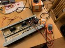
A variac has been sourced! I'll then power up to 100Vac, take readings from where I can (no schematic or layout) and report them back here in case anyone else wants to save a 20 year old transistor amp....
 

tristanc

New Member
Joined
Oct 6, 2019
Messages
10
Reaction score
6
OK, for the benefit of anyone else looking in the future:

Japan PT spec: 100Vac Primary -> 33-0-33 Secondary

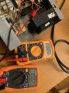
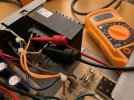
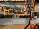
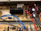
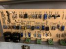
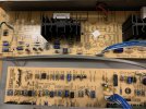
I then measured ~+/-43Vdc at a couple of places close by the rectifier. But without removing the board and tracing the circuit I have no idea where those readings where.

I'll now be looking for a cheap replacement (100VA or so) that physically fits.
 

Attachments

  • IMG_2274.jpeg
    IMG_2274.jpeg
    409.2 KB · Views: 6
  • IMG_2273.jpeg
    IMG_2273.jpeg
    379.4 KB · Views: 6
  • IMG_2272.jpeg
    IMG_2272.jpeg
    391.5 KB · Views: 6
  • IMG_2271.jpeg
    IMG_2271.jpeg
    401.7 KB · Views: 8
  • IMG_2270.jpeg
    IMG_2270.jpeg
    369.2 KB · Views: 6
  • IMG_2269.jpeg
    IMG_2269.jpeg
    447.6 KB · Views: 6
  • IMG_2268.jpeg
    IMG_2268.jpeg
    461.4 KB · Views: 6

tristanc

New Member
Joined
Oct 6, 2019
Messages
10
Reaction score
6
Had a quick look, it seems there are a couple of options for PT:

- a 115/230VAC to 36V CT - just run it a bit over voltage
- use a 115VAC to 16VAC CT and connect 230VAC instead to get 32VAC CT (likely a bit over).

Both are ~100VA and roughly the right size. Tempted for the latter option as it will be closer to 33VAC.
 

tristanc

New Member
Joined
Oct 6, 2019
Messages
10
Reaction score
6
For those in the future looking to replace the PT in a Bass State B65, the Hammond 186F36 seems to work well. And is cheap.


You need to drill out the rivets of the old PT, drill two new mounting holes for the new PT, then snip off the existing spade connectors and solder the wires appropriately. The change is invisible from the outside.
 

Latest posts


Top