Started to build a JTM45/100 clone, based on the Marstran schematics by BKW, 5/12/07 (the so called "Hendrix/Dickinson" amp, Marshall #7026). This wont be a faithful replica. Instead, I will make some up-dates to the circuit (safety, reliability). The exterior I plan to keep close to original, with modern parts.
- Marstran trafos (still waiting for delivery, x-mas gift in best case, but probably next year)
- MetroAmp chassis from Valvestorm
- Boards, turrets, sockets, selectors, pots, etc. from Modulus
- Standard parts from Mouser and Digi-Key
- Still haven't ordered valves. Matched TAD quad seems reasonable, together with Psvane ECC83.
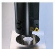
Got most part and dry-fitted what I've got. Octal sockets don't fit the chassis. Need to get a 30 mm step-drill to make the holes about 1 mm bigger. There will be some more work to layout bias sampling points, fit the IEC socket, etc. Some pictures below.


Prelude
 www.marshallforum.com
Coda
Some related/relevant links:
https://www.marshallforum.com/threads/my-45-100-jh-clone.101156/
https://www.marshallforum.com/threads/not-another-jtm-45-100.124630/
https://www.marshallforum.com/threads/building-a-jtm-45-100-malcolm-young-kt66.117350/
https://www.marshallforum.com/threads/dc-or-ac-standby-switch-for-jtm45-100-clone.135476/
https://www.marshallforum.com/threads/questions-on-bias-sampling-resistors-jtm45-100-clone.135600/
https://www.marshallforum.com/threads/nfb-resistor-for-jtm45-100-clone.137042/
www.marshallforum.com
Schematics, voltage chart, component list, and bias calculations and measurements for the completed amp:
- Marstran trafos (still waiting for delivery, x-mas gift in best case, but probably next year)
- MetroAmp chassis from Valvestorm
- Boards, turrets, sockets, selectors, pots, etc. from Modulus
- Standard parts from Mouser and Digi-Key
- Still haven't ordered valves. Matched TAD quad seems reasonable, together with Psvane ECC83.
Got most part and dry-fitted what I've got. Octal sockets don't fit the chassis. Need to get a 30 mm step-drill to make the holes about 1 mm bigger. There will be some more work to layout bias sampling points, fit the IEC socket, etc. Some pictures below.
Prelude
Help me specify a JTM45/100 clone
I would like some help to specify a JTM45/100 clone, “Hendrix” circuit. Been searching Internet, and I see some of the frequent usernames here coming up, but some info is no longer available and there seems to be changes in availability for e.g. trafos from different suppliers. Therefore, I’m...
www.marshallforum.com
Coda
Some related/relevant links:
https://www.marshallforum.com/threads/my-45-100-jh-clone.101156/
https://www.marshallforum.com/threads/not-another-jtm-45-100.124630/
https://www.marshallforum.com/threads/building-a-jtm-45-100-malcolm-young-kt66.117350/
https://www.marshallforum.com/threads/dc-or-ac-standby-switch-for-jtm45-100-clone.135476/
https://www.marshallforum.com/threads/questions-on-bias-sampling-resistors-jtm45-100-clone.135600/
https://www.marshallforum.com/threads/nfb-resistor-for-jtm45-100-clone.137042/
Volume drop at 10 (DIY clone)
There's a sudden volume drop right before I hit the max stop end on the High Treble volume pot on my newly built JTM45/100 clone. It's been consistent the few time I tested. Volume increases as expected when I turn the pot, until this drop happens. It's also independent of guitar input volume...
www.marshallforum.com
Schematics, voltage chart, component list, and bias calculations and measurements for the completed amp:
Attachments
Last edited: