• We are looking to make improvements to the Classifieds! Help us determine what improvements we can make by filling out this classifieds survey. Your feedback is very appreciated and helpful!

    Take survey

Fire in Marshall2203

  • Thread starter rbotn
  • Start date
  • This site may earn a commission from merchant affiliate links like Ebay, Amazon, and others.

rbotn

New Member
Joined
Jun 17, 2015
Messages
25
Reaction score
4
Hi
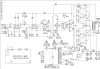
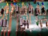
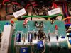
I got an amp Marshall 2203-1 with effect card from a customer who has burned. As you can see at the attached pictures it is R31/32 in the filament system, and R17/18/20 in the feedback/cathode of the phase inverter tube, and R11 the cathode resistor at V2, the second valve in the preamp witch are burned. Any suggestions?
 

Attachments

  • Inkedmarshall2203x_LI.jpg
    Inkedmarshall2203x_LI.jpg
    948.2 KB · Views: 57
  • marshall 3.jpg
    marshall 3.jpg
    736.4 KB · Views: 58
  • marshall 2.jpg
    marshall 2.jpg
    847.3 KB · Views: 58
  • marshall 1.jpg
    marshall 1.jpg
    862.9 KB · Views: 56

Dogs of Doom

~~~ Moderator ~~~
Staff Member
Joined
Aug 2, 2012
Messages
33,004
Reaction score
55,820
Location
Los Angeles
looks like more than that...

What does the underside of the board look like?
 

cruisemates

Active Member
Joined
Dec 16, 2010
Messages
139
Reaction score
41
Some of those electrolytic caps look pretty suspect, too. I wonder what happened?

This is a reissue and has a hum balance control (which the original do not have). Since those resistors fried and that control is right off the PT, it looks like it might have started there. Not sure, though.
 
Last edited:

Max Gahne

Well-Known Member
Joined
Dec 1, 2020
Messages
313
Reaction score
466
Some of those electrolytic caps look pretty suspect, too. I wonder what happened?

This is a reissue and has a hum balance control (which the original do not have). Since those resistors fried and that control is right off the PT, it looks like it might have started there. Not sure, though.

And the schematic shows the hum balance tap has a center tap and says N.C. - no connection. I might look that it didn't get to ground somehow. Next I'd see that there's resistance in the hum pot, that it didn't short and that the wiper is connected to ground. I'd really be curious about that hum thing.
 
Last edited:

cruisemates

Active Member
Joined
Dec 16, 2010
Messages
139
Reaction score
41
Yeah, most of the parts that fried were tied to ground - including one that fried after the one next to it fried which was tied to ground. Those pictures are "I can't look away..." The hum control Rs are R31 and R32 in Pic 1 and they look right fried. That little hummypot is probably gone too, and D1 doesn't look too good.
 

Pete Farrington

Well-Known Member
Joined
Jan 18, 2021
Messages
3,248
Reaction score
4,281
Location
Staffordshire UK
Maybe a power valve shorted, eg screen grid to heater, such that something at HT potential connected to the heater, sending HT fault current through the heaters to circuit common 0V. A CT on the PT’s heater winding can take that, and pop the HT fuse before collateral damage is done. But not low power heater balancing resistors / humdinger pot.
The balancing resistors will blow instantly, probably faster than the T type HT fuse, so the shorted valve will then pull the heater string up to HT voltage. That stresses the heater - cathode insulation of all the other valves, often damaging them to some degree. Those that actually short then have their cathodes pulled up to HT, blowing resistors in their cathode circuit, as seems to have happened here.

It is best to assume that all the valves are scrap even if any are still functional, as due to h-k leakage, they’ll probably cause heater buzz interference in an amp's signal path.

This is a great example of why I prefer to use 5w high voltage heater balancing resistors if there’s no CT on the PT’s heater winding. My view is that they have to hold up to fault current and maintain the heater circuit’s 0V reference long enough for the HT fuse to blow. But certainly it’s preferable for the HT to the valves to be via a F / quick blow fuse.

The other view (that a lot of clever people hold) is that they prefer the resistors to blow, in order to protect the PT.

I wonder how this power valve failure mode plays out in amps that have DC elevated heaters:hmm:
 
Last edited:

KraftyBob

Well-Known Member
Joined
Sep 5, 2017
Messages
2,415
Reaction score
3,603
Location
Chicago Suburbs - USA
Maybe a power valve shorted, eg screen grid to heater, such that something at HT potential connected to the heater, sending HT fault current through the heaters to circuit common 0V. A CT on the PT’s heater winding can take that, and pop the HT fuse before collateral damage is done. But not low power heater balancing resistors / humdinger pot.
The balancing resistors will blow instantly, probably faster than the T type HT fuse, so the shorted valve will then pull the heater string up to HT voltage. That stresses the heater - cathode insulation of all the other valves, often damaging them to some degree. Those that actually short then have their cathodes pulled up to HT, blowing resistors in their cathode circuit, as seems to have happened here.

It is best to assume that all the valves are scrap even if any are still functional, as due to h-k leakage, they’ll probably cause heater buzz interference in an amp's signal path.

This is a great example of why I prefer to use 5w high voltage heater balancing resistors if there’s no CT on the PT’s heater winding. My view is that they have to hold up to fault current and maintain the heater circuit’s 0V reference long enough for the HT fuse to blow.
The other view (that a lot of clever people hold) is that they prefer the resistors to blow, in order to protect the PT.

I wonder how this power valve failure mode plays out in amps that have DC elevated heaters:hmm:
[Off Topic]

Welcome to the forum, Pete. I've seen you on The Gear Page and you offer some excellent advice. It's great to see you here as well!
 

johan.b

Well-Known Member
Joined
Feb 21, 2015
Messages
2,311
Reaction score
3,404
Location
Södertälje, Sweden
... someone hotswapped the preamp tubes, tried to push in a tube with pins/ legs misaligned, causing shorts on both filament and other things?...(notice the question mark... it's a guess, not a statement..:) )
J
 
Last edited:

neikeel

Well-Known Member
Joined
Feb 12, 2014
Messages
8,462
Reaction score
9,634
My guess is failure of the pot. Heaters tried to find alternative routes to ground.
You will just have to go through the amp methodically and replace blown parts. Personally I would hard wire the 100k resistors to ground and delete the pot.
Agree with Pete- you have to assume all tubes are toasted.
 

Max Gahne

Well-Known Member
Joined
Dec 1, 2020
Messages
313
Reaction score
466
Thinking about this, if I were the shop I'd have to tell the customer he has around 250$ of time in this thing just to get it to where we could determine if the PCB is still good and what all else is fried. Feel that out with the customer and then may well just give it back to him. As a hobbyist I'd like to learn what happened but if I were a business it becomes relative to money.
 

Latest posts


Top