JCM2000 DSL100 popping R9 resistor

  • Thread starter jshort74
  • Start date
  • This site may earn a commission from merchant affiliate links like Ebay, Amazon, and others.

jshort74

New Member
Joined
Nov 10, 2022
Messages
12
Reaction score
6
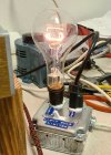
I've got a 2009 JCM200 DSL100 (issue 20 main board) that suddenly lost all of it's volume. It's very faint on 10. During my troubleshooting I completed an insulation breakdown test and found the values all stayed very consistent. While doing that I found that the R9 resistor had burnt and also damaged the trace on the board directly under it. I removed the main board from the chassis, replaced the R9 resistor (you can see the new Grey one in the image) and bypassed the burnt trace with the black insulated 18ga solid wire you can also see in the image. It played well for a couple of hours then the R9 popped again.

I've been doing a lot of reading on this forum, but I can't seem to find this issue. I could use some help figuring out why the R9 keeps popping.

One thing I'm planning to try: I noticed that the Uxcell 1 ohm, 1W 5% Tolerance Carbon Film Resistors I ordered off of Amazon seem to have thinner conductor wires than the resistor that came off the board. It makes me think I was sent 0.5w resistors instead of the 1w I ordered. I ordered those specs because of what the Issue 7 schematic I have, told me it should be. (can't find an issue 20 schematic). Now, I've ordered some 1 Ohm Resistors, 3W 1% Tolerance Metal Film Resistors to put in this time. Am I way off with this? Is this a bad idea?

Not brand new working on electronics, first time troubleshooting an amplifier but definitely not new to troubleshooting problems. I'd appreciate any direction you all can give me!
Thanks!


1668799789664.jpeg
 

Dogs of Doom

~~~ Moderator ~~~
Staff Member
Joined
Aug 2, 2012
Messages
32,943
Reaction score
55,624
Location
Los Angeles
I have an older ISS board & replaced my R6 & 9 w/ 2 watt resistors, for that very reason, although, mine only popped once, that I know of, but... I've seen many threads on here, w/ multiples of those resistors popping.

So, IMO, there's probably something else going on & wouldn't just put a stronger resistor in, until you figure out what's wrong w/ it.

Have you done the 16 ohm ground fix?

also, the bias pot's themselves go bad, which causes bias drift, similar to the bad board conductivity.

Have you done the stable bias mod? Some say that they've had to do that, even after replacing the main board...
 

Dogs of Doom

~~~ Moderator ~~~
Staff Member
Joined
Aug 2, 2012
Messages
32,943
Reaction score
55,624
Location
Los Angeles
I originally replaced the resistors w/ 5 watt, but, was told by quite a few trusted guys on here, that, that's not a good Idea, so I went w/ the 2 watters...

The resistor doubles as a fuse, so that it pops, instead of causing damage further down line.

this is the one I bought:

VISHAY DALE - CPF21R0000FKE36 - RESISTOR; METAL FILM; 1 OHM; 2W; 1%


As an Amazon Associate we earn from qualifying purchases.

jshort74

New Member
Joined
Nov 10, 2022
Messages
12
Reaction score
6
I
I have an older ISS board & replaced my R6 & 9 w/ 2 watt resistors, for that very reason, although, mine only popped once, that I know of, but... I've seen many threads on here, w/ multiples of those resistors popping.

So, IMO, there's probably something else going on & wouldn't just put a stronger resistor in, until you figure out what's wrong w/ it.

Have you done the 16 ohm ground fix?

also, the bias pot's themselves go bad, which causes bias drift, similar to the bad board conductivity.

Have you done the stable bias mod? Some say that they've had to do that, even after replacing the main board...
Yep, I tied the input grounds together on the underside of that board when I had the main board out to change the R9 resistor.

I haven't changed anything with the bias pots.

Thanks for linking those resistors.
 

Dogs of Doom

~~~ Moderator ~~~
Staff Member
Joined
Aug 2, 2012
Messages
32,943
Reaction score
55,624
Location
Los Angeles
one thing that could be causing your grief as well, is if a tube is arc'ing, even though not yet failing. Pull the power tubes & check the bases for any soot, or other signs of fire across them...

one thing to note, the stable bias mod kit, does not change the bias trim pot's, so they are 2 distinct things.

another note, change both R6 & R9, as they are the same thing, the opposite side of the push/pull tube set. You want them to be the same, so each side of the bias behaves the same.
 
Last edited:

jshort74

New Member
Joined
Nov 10, 2022
Messages
12
Reaction score
6
Well, that didn't go so well! I replaced R6 and R9 with 1 ohm, 3W resistors. Everything was good when I turned the power on the warm it up. When I hit the standby, the R9, R8, R78 and Mains fuse all blew. R6 looks good (1.3 ohm).

I pulled the tubes and I didn't see any signs soot, arcing or anything else before I put it back together after changing R6 and R9. I've double checked all of the connections on the main board to see if maybe got a couple of them switched and I'm 99% sure I've got them all in the correct spots.

What do you recommend next? How would you recommend addressing the bias trim pots?

Thanks!
 

Pete Farrington

Well-Known Member
Joined
Jan 18, 2021
Messages
3,238
Reaction score
4,268
Location
Staffordshire UK
Remove output valves and check that a reasonable bias voltage (eg -40V) is being provided at each socket terminal #5.
Monitor that voltage as the bias trimmer is adjusted over its full range.
Initial power ups after repairs (without then with valves) should be via a light bulb limiter. Bulb wattage not to be higher than the amp’s rated max audio power output.
 
Last edited:

jshort74

New Member
Joined
Nov 10, 2022
Messages
12
Reaction score
6
Remove output valves and check that a reasonable bias voltage (eg -40V) is being provided at each socket terminal #5.
Monitor that voltage as the bias trimmer is adjusted over its full range.
Initial power ups after repairs (without then with valves) should be via a light bulb limiter. Bulb wattage not to be higher than the amp’s rated max audio power output.
Thanks for your input Pete. When I did the Insulation Breakdown Test on terminal #5 before changing the R9 the first time, I measured (With stand by switch off) -42.55 vdc, -42.59 vdc, -41.99 vdc & -42.11 vdc. Then I left it on for an hour and checked again and read (With stand by switch off) -42.14 vdc, -42.10 vdc, -41.56 vdc & -42.52 vdc. Then I turned the stand by switch on and measured -42.31 vdc, -42.28 vdc, -41.77 vdc & -42.78 vdc. I though those seemed stable, what do you think? Should I perform the test again? Should I replace the blown resistors before testing again?

When monitoring the voltage on terminal #5 while turning the bias potentiometers through there full range, what voltages should I see?

I'm just now reading about light bulb limiters. I should have the parts to put one together laying around. It seems like I probably could have prevented the most recent thermal event especially if I had used the light bulb limiter with my variac.
 
Last edited:

jshort74

New Member
Joined
Nov 10, 2022
Messages
12
Reaction score
6
Well, I'm kicking myself bigtime now. I just noticed that I had left W14 and CON14 disconnected.
Measure primary winding resistance of the OT (W3 > W5, W4 > W5, W3 > W4) with Powertubes removed.
I bet one side gives you an awkward reading...
Thank you for your help! Can you spoon feed me a little here? I know where W3, W4 and W5 are on the OT but where to I place the leads on my VOM to test the resistance for each?
 

jshort74

New Member
Joined
Nov 10, 2022
Messages
12
Reaction score
6
Well, I'm really kicking myself now. I just noticed that I had W14 and CON2 disconnected from the main board. I'm assuming that was part of the problem that caused R9, R8, R78 and Mains fuse all to blow.
 
Last edited:

jshort74

New Member
Joined
Nov 10, 2022
Messages
12
Reaction score
6
Well, I've cleaned up the board and replaced R8, R9, R78 and the fuse. I built myself a lightbulb limiter, plugged the amp into it and turned on the power to the amp. The 300w bulb lit up a bit at first then dimmed to nothing while I let it warmup. When I turned on the standby switch, the bulb lit up but then dimmed, but not all the way. It sounds good when I played through it. Is this what I should expect the limiter to do with this amp and bulb combination? Is it good to go?

Thanks!
 

Attachments

  • 20221128_194602 (2).jpg
    20221128_194602 (2).jpg
    231.2 KB · Views: 4

Dogs of Doom

~~~ Moderator ~~~
Staff Member
Joined
Aug 2, 2012
Messages
32,943
Reaction score
55,624
Location
Los Angeles
w/o the limiter, fire it up w/o the power tubes in & make sure it doesn't do anything like blow a fuse again...

If it seems fine, plop the tubes back in & bias it...
 

jshort74

New Member
Joined
Nov 10, 2022
Messages
12
Reaction score
6
Thank
And seriously......replace those bias pots.
They're cheap and they WILL fail with time and then you'll be fixing all kinds of stuff.
Thank you for that feedback! I'm sold on replacing them. What should I replace them with and where do I buy them?
 

jshort74

New Member
Joined
Nov 10, 2022
Messages
12
Reaction score
6
amprepairparts.com

Part #POT-TR22K

They're only $tree-fiddy a peice.
Thank you! It looks like these are exactly the same as the originals. Do these just have a certain life expectancy and you just want to proactively replace them or have these new one's been re-engineered so that once you replace them, you're good for the long term?
 

Latest posts


Top