JCM900 4500 EL34 Red plating/run away bias current

cozmacozmy

Active Member
Joined
Apr 9, 2011
Messages
179
Reaction score
119
Location
West Michigan
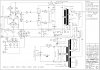
Hello, been lurking these forums for years now and finally come across a problem that I have no clue what the cause is. I have a 1990 4500 JCM 900 DR with Sovtek EL34wxt (originally an EL34 model, unmolested and extremally clean inside) that I've had for many many years. I have not played the amp in a long time and figured I would buy a plate current probe to measure the bias to just see what it was. I wasn't aware of any problems prior to this testing and I have triple checked to make sure I didn't cause this issue while removing the chassis to do the bias testing... I just don't see how I could of caused this??? I did not play this before pulling the chassis so I am not sure if the time since playing this (years ago) is what failed, and just started to show up...

So... When I hooked up the 2 plate current bias probes under the tubes & hooked to my ammeter (A snap on Vantage pro graphing multi meter) on the ma scale and with my Fluke 88 on the voltage pin #3 to monitor plate voltage. When I went to turn it on, the voltage starts out at 480v and starts dropping when the tubes start flowing. The plate current rises to around -35ma as soon as the tubes warmed up and started flowing. The voltage starts dropping at this same time and as it gets around 400v the current is -80ma and getting worse by the second. At this time the plates start to go red. Adjusting the bias pot has no effect on the readings at all!

From all the reading I have done and pin voltage testing, the only thing I can see is the missing negative control grid voltage. Visually I don't see any burnt components, leaking caps (although all are original) I measure the 22k across the bias pot. I even put in a pair of GT El34 from my buddy and the red plating was even worse with the current hitting -330ma at one time and an extremely red plate. The amp smells extremely hot too while this is all going on! Tried this with and without all the 3 preamp tubes also. I have swapped tubes side to side and to my buddies GT EL34. Even pulled the preamp tubes and nothing seems to change anything.

With no power tubes in place I get
pin 3 482v
pin 4 482v
pin 5 -.007 to -.010 depending on where the bias pot is at. (this is the only difference i see moving the bias pot)

Shouldn't I be seeing around -35v on pin 5

Any ideas at to what I should do to pin point this down?
 

cozmacozmy

Active Member
Joined
Apr 9, 2011
Messages
179
Reaction score
119
Location
West Michigan
Ps... With the amp turned off and the bias probe plugged into the ammeter (turned off) still and with the power cable attached to the amp... I get a buzz/hum through the speakers. Unplugging the power cable or the ammeter leads makes it go away but comes right back again when plugged back in.
 

tschrama

Well-Known Member
Joined
May 15, 2010
Messages
1,539
Reaction score
889
Location
Netherlands
Ditch the probe.

You are grounding pin3 , the anode, with the Multimeter set to mA?

Without EL34s installed measure the plate voltage ( not mA!) should be around +480V and on pin3 and grid voltage on pin 5 should be around -40V.

There is no point in installing the power tubes or trying to bias them unless you have about -40V on the grids.

Maybe you accidentally shorted your grids to gnd while trying to measure the grid voltage while your multimeter was set to mA? Maybe this fried your bias circuit.

and please dont call it an ammeter; that implies a short while a voltmeter is a high impedance connection. Its a multimeter set to mA, A, mV or V etc. Quote ur settings and connections.
 
Last edited:

neikeel

Well-Known Member
Joined
Feb 12, 2014
Messages
8,455
Reaction score
9,616
First thing is that given lack of use recently and run away bias I would suspect It is probably failing bias caps.
However with virtually no pin 5 voltages means you need to check the bias feed diode and measure the voltage from the bias supply.
What are your voltages either side of that cap c15
it puzzles me why you might have a cap there that might cut bias voltage if it fails!!
 
Last edited:

Pete Farrington

Well-Known Member
Joined
Jan 18, 2021
Messages
3,226
Reaction score
4,256
Location
Staffordshire UK
Could it be the C15 x cap (or safety cap?) near the bias pot?
If referring to component references, include the appropriate schematic.
That cap is also C12 on a different revision.
But yes, if that’s bad, the amp will wreck the EL34s in short order.
It’s massively stupid that the amp doesn’t have a HT fuse that will protect it from such reasonably foreseeable issues :mad:
As above, never put valves in an amp that doesn’t have bias voltage.
Especially if the valves belong to a friend (now ex!)
https://www.thetubestore.com/lib/th...arshall-JCM900-Dualrev-50W-4500-Schematic.pdf
 
Last edited:

Gunner64

Well-Known Member
Gold Supporting Member
Joined
Nov 16, 2013
Messages
9,189
Reaction score
15,582
Location
Midwest, USA

Pete Farrington

Well-Known Member
Joined
Jan 18, 2021
Messages
3,226
Reaction score
4,256
Location
Staffordshire UK
I'm pretty sure that amp an ht fuse and led fail indicator for the power tubes.
Oh yeah, sorry, I missed the fuse on the output valves cathode returns.
Thanks for pointing that out. It did seem weird so I should have investigated further. The HT fuse I did see before is after the feed to the OT, and that threw me off the scent :)
Obviously there’s a problem with the cathode fuse if it doesn’t blow in response to bias failure.
What value is in there?
Actually, it would take quite a prolonged time for the specified T500mA fuse to blow.
A T type fuse is inappropriate there, as in normal operation, there shouldn’t be any current surges much in excess of 500mA.

Internal output valve faults that short an electrode at HT potential to the heater are fairly common. There doesn’t seem to be much mitigation for that.
 
Last edited:

cozmacozmy

Active Member
Joined
Apr 9, 2011
Messages
179
Reaction score
119
Location
West Michigan
Thanks guys,
The meter plugged in is what was causing the hum from the speakers. I am sure there was no short with measuring the grid voltage. If I understand the C15 X safety cap is they short when they fail? Is this correct? All fuses are good. The ammeter mention is from my automotive background. I've been an auto mechanic for over 30 years. I added the wiring diagram that I have been using.

I have no negative voltage on pin 3 of either tube.
Voltage at D1 is 0v AC on one side of the diode and .163mv AC on the other and 0v DC on either side.
I do have 207v DC feeding the C15 x cap from the stand by switch as it comes out of the mains transformer.

From what I can see is that C15 went bad??? I order a one and a set of new tubes the other day. I found quite a few posts through the net saying how everything was fine with their amp and when they pulled the chassis just to test the bias that C15 went bad on them. The banging around when removing the chassis made these go bad? From what I see they are not rated for the amount of voltage that is being sent through them. I see a lot of people use a Xicon 630v capacitor to replace this safety cap.

Thanks again everyone. I will update this when I get the new one in. Should be here sometime next week.
 

Attachments

  • 900a.jpg
    900a.jpg
    215.5 KB · Views: 22

neikeel

Well-Known Member
Joined
Feb 12, 2014
Messages
8,455
Reaction score
9,616
Yes an x type safety cap should fail short, I presume that what is supposed to happen is that it goes over current and take the anode fuse out rather than chop the bias supply itself. Seems complicated to me, but then I am not an EE!
Pete F will know better and his comment re a fast blow fuse T type is probably a good one.
 

cozmacozmy

Active Member
Joined
Apr 9, 2011
Messages
179
Reaction score
119
Location
West Michigan
I think we caught it just as it was failing. The ma never went over 300ma and that was just for a few secs until I hit the power switch to off.
 

cozmacozmy

Active Member
Joined
Apr 9, 2011
Messages
179
Reaction score
119
Location
West Michigan
That's what I've seen many say. But that this is a 630v cap in later models and that Marshall made a mistake putting is such a low voltage rating safety cap.

Is that right?
 

anitoli

Well-Known Member
Joined
Jul 9, 2011
Messages
12,335
Reaction score
21,311
Location
Lewiston, Maine U.S.A.
That's what I've seen many say. But that this is a 630v cap in later models and that Marshall made a mistake putting is such a low voltage rating safety cap.

Is that right?
I don't think the 250v cap is that problematic my 6100's use the same and have going strong for ever. Prolly they just ran out of 250's and all they could get was 630's or it's shut down the line, so thet used them. That said a 630v isn't going to hurt anything.
 

cozmacozmy

Active Member
Joined
Apr 9, 2011
Messages
179
Reaction score
119
Location
West Michigan
Still waiting for the caps and tubes to come in. Tracking said they would be here yesterday but they didn't show up.
 

XTRXTR

Well-Known Member
Joined
Feb 14, 2021
Messages
1,383
Reaction score
1,789
Location
Some City, USA
I don't see a bleed resistor on the reservoir cap on the schematic. You may have one not shown on the schematic. You should add one about 100 to 220k 2w. This bias circuit should have one according to Merlin. Since there is no CT on the HT a path needs to be provided to discharge the filter caps or you could experience a problem if the power blinks out or an "On Off On" situation happens - the negative bias voltage would not be present when the amp is back on but the HT would still be present. This will cause an over current condition on the anodes of the power tubes. If your in the middle of some power chords on the guitar in this condition that could be enough to blow the tubes.

Separately:
And just putting this out there, could such a condition cause a grid current situation that caused the 250V bias coupling cap failure? I'm just throwing darts on this part, I only just learned about this bias circuit. Assuming no neg bias voltage the only grid voltage would be AC of the guitar signal at MAX dissipation levels. If that happens you could get grid currents that have to go down the Leak path. With a large 50-60Hz AC from the HT on one side of the cap and the large current on the other side essentially a modulated distorted wave form across the 250V cap. Is that a viable explanation?
 

Latest posts


Top