• We are looking to make improvements to the Classifieds! Help us determine what improvements we can make by filling out this classifieds survey. Your feedback is very appreciated and helpful!

    Take survey

JVM410H BIAS problem after modding and retubing - SOLVED :-)

The Creator

New Member
Joined
Apr 15, 2017
Messages
8
Reaction score
7
Location
Rygge, Norway
Hi there experts, I had my JVM410h dropped to the ground from 3 feet after a gig, and it was not played until it was checked.
So when doing the check, I would do some moddifications as well.
First I saw that the R26 was blown, this could be a bad tube. The tubes were originale from 2008 so i guess it was time to fail!
I deassembled everything and did NFB mod, Resonance mod, C83 with switch, put in a noisegate, and changed several resistors to metal-film and some diodes to lower the noise. All these tips can be found in the MOD Bible.
When all was completed, I started to do some voltage measurements, without tubes. This I looked up in a post in the forum.
This was to check that all the powertubes had right voltages, and were bias-able.
Result after 30min warmup:
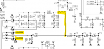
In StBY=off: Pin 5 =adjustable from -29 to-47V, Pin 3 Platevoltage=470V, Pin 2=67V. All these values are OK right?
I put the new set of tubes in, and measured again:
StBy= ON Pin 5 =adjustable from -29 to-47V, Pin 3 Platevoltage=419V, Pin 2=56V. Voltages on pin 3 and 5 dropped, NORMAL ??
Measured voltage across screen resostor to +10V and above !!!
Measured voltage at BIAS connector to +100mV and above !!!
I shut down the amp fast, and took the new tubes out, if they could be the reason.
Tested again with old tubes, and the same result as above. Shut down fast.
Tested agin with only one set of powertubes V3&V4 and preamp tubes, same result.. BIAS is way to high !!!

I have not changed any resistor values in the powersection, only the NFB, this was set to 47k at test.

Can anyone tell me what is going on here???
Can I test the amp with only powertubes in, to see if there is problem with the preamp tubes?
 

tschrama

Well-Known Member
Joined
May 15, 2010
Messages
1,539
Reaction score
889
Location
Netherlands
Set bias to -55volt. And see what happens. Adjust bias supply resistors if nessecerry.
 

Ivan H

Well-Known Member
Joined
Jan 17, 2021
Messages
135
Reaction score
264
I have a suggestion (won't help any with your current situation), but just for future reference,,,, when you have an amp with questionable serviceability, first ensure the amp is ensured to be in or repaired to fully serviceable condition before attempting any modifications. Cheers
 

anitoli

Well-Known Member
Joined
Jul 9, 2011
Messages
12,335
Reaction score
21,311
Location
Lewiston, Maine U.S.A.
Sounds like every 6100 that hit my bench with mods, they didn't work right.

My suggestion would be to put it back to stock.
 

Spanngitter

Well-Known Member
Joined
Jan 22, 2019
Messages
515
Reaction score
565
Location
Upper Palatinate / Bavaria
Love that when people with zero clue on how a tube amp works start modding their units.
The principle of Bias adjustement resp what the Voltage applied to Pin5 in conjunction with plate voltage does is clear to you?
Adjust to max negative Voltage @Pin5 and then remeasure at the Bias Test Point. If still >100mV on each side then you boobood big time when modding and reassembling and you might now have a massive door stopper.
Tracing back what you messed up is basically impossible from remote, it would require a detailed description and pictures plus capability on you side to follow recommendationas and deliver detailed measurements and even then there is chance that you accidentially killed something viable required for the amps health.
 

Pete Farrington

Well-Known Member
Joined
Jan 18, 2021
Messages
3,247
Reaction score
4,280
Location
Staffordshire UK
I had my JVM410h dropped to the ground from 3 feet after a gig, and it was not played until it was checked.
So when doing the check, I would do some moddifications as well.
First I saw that the R26 was blown
R26 looks to be the 1ohm cathode current sensing resistor for two of the output valves. If that was blown, ie open circuit, it seems to indicate that you played the gig with only one of the push pull sides working, which would cripple the amp’s output, maybe 5W before it farted out?


neikeel

Well-Known Member
Joined
Feb 12, 2014
Messages
8,462
Reaction score
9,634
Isn’t pin 2 supposed to be heater 3.15 to ground? same as pin 7. 8&1 are ground or to bias test resistor point. Pin 4 is screens. Pin 6 is NC unless used as bridge for screen hook up.
Before going any further please clarify.
 

william vogel

Well-Known Member
Joined
Dec 18, 2016
Messages
1,338
Reaction score
1,877
Sounds like it’s oscillating because the screen current has moved up and the plate voltage is down. Measure AC voltage across the speaker output to verify no output voltage. Your mod could have caused the amp to begin amplifying with no input signal. Also your pin 2 measurements are in AC volts because it’s the heater. Pin 2 could be an elevated DC but it’s got AC heaters.
 

The Creator

New Member
Joined
Apr 15, 2017
Messages
8
Reaction score
7
Location
Rygge, Norway
Hi guys and thanks for all reply, and the good hints.
For those who judged my knowledge rather than coming with a solution, should think before writing....
I have worked with electronics in 35 years, and still handles volt & current as my daily work. I admit that my knowledge in tube amps is abit low, but I always do good research before I dive into new projects. I have watched tons of videos, how an amp works, and I felt pretty comfortable to open and do modifications to my amp.
Problem is now solved :) With help from a nice guy that did not missjudge me, and my skills.
Solution, and what I did...
- I double checked every resistor for it's value, all were correct
- checked every disconnected lead for it's correct position, all in right place
- I removed all tubes, turned ALL volume and gain to zero, and turned on the amp
- turned bias potmeters to -47mV, (max negative voltage)
- I measured every voltage, on the tube-pins, and on resistors. every voltage was as it should be :)
- I checked that the bias potmeters were adjusting the voltage correctly
- turned the amp off, took a 5 min break
- put in all the new tubes, turned the amp on, let it idle for 10 min before turning standby to ON
- I set up two multimeters for the bias voltage, easy to see the differences
- turned up bias voltage to 75mV(recommended voltage for 65% of dissipation) let it warm up for 30 minutes
- as it warmed up I checked voltages of every tube-pin and voltages across the screen resistors
- after 30minutes everything was as normal :) and I connected my guitar and gave it a play for an hour,

SUCCESS: This amp just got even better than before, now all modes are playable, and the noisegate I fitted for OD RED modes was excellent. Clean channel was crystal clear and had lot of volume, ( that it lacked before the mod). The amp has much lower noise and feels as a whole new amp with lot of power to blast audience away :)

Again, many thanks for sharing your expertise and knowledge
 

The Creator

New Member
Joined
Apr 15, 2017
Messages
8
Reaction score
7
Location
Rygge, Norway
Hi Travis398, The problem was that I had set the P5 voltage to high at start (-34V). When I set P5 at -47V and then adjustet the BIAS potmeters to get proper BIAS voltage measured at the test-points. Set to 76mV and all works fine.

I'm impressed how this mod "tamed" the beast :) and the sound in every mode is now playable.
 

Latest posts


Top