Marshall 9200 bias and balanced phase inverter

  • Thread starter andrex88
  • Start date
  • This site may earn a commission from merchant affiliate links like Ebay, Amazon, and others.

andrex88

Member
Joined
Aug 23, 2020
Messages
87
Reaction score
16
Hi everyone, I have a Marshall 9200 dual mono, I would like to learn how to adjust the bias after replacing both the power tubes and the phase inversion and pre tubes. Not having any data available, I contacted Marshall and regarding this amplifier they gave me this answer;

(The 9200 isn't as straight forward as a standard valve amp…
It requires setting up using a signal generator, a dummy load and an oscilloscope.
The Bias should be set for 35mA per valve using RV1 & RV4 with respect to which channel they supply.
The amplifier will also require balancing using RV2 & RV3 with respect to the channel you are balancing).

I also don't understand why in the answer that Marshall gave me in the email he calls the RV valves in the diagrams they are not mentioned with RV. Now I have had some occasion to adjust the bias on simpler amplifiers such as the TSL60, but I don't have much experience with this 9200 and would like to learn. I noticed that there is a potentiometer for the balance I think for the phase inverter and a pot bias for the final valves, I don't understand if there is a procedure if you start first by adjusting the phase inverter balance and then the bias of the power valves. How should the adjustment procedure take place? I connect an analog bf generator to the input of the amp but I don't know what frequency to set it to, then I connect a dummy 8 ohm load instead of the speakers, at this point with a multimeter I should connect to pin 8 of the 5881. With the oscilloscope I imagine you need to check the alignment of the sinusoid. Since the amplifier is mine I have all the time and patience to learn, I don't know if any of you have ever had to deal with this model.


Pete Farrington

Well-Known Member
Joined
Jan 18, 2021
Messages
3,241
Reaction score
4,273
Location
Staffordshire UK
I don't understand if there is a procedure if you start first by adjusting the phase inverter balance and then the bias of the power valves. How should the adjustment procedure take place?
Set bias first, at idle = no signal.
When done apply a signal to achieve maybe 50% power output. Frequency doesn't really matter, whatever you preference from 100Hz to 10kHz.
1kHz may be a happy mid point.
Tweak the balance to obtain the most symmetrical output waveform when scoping the dummy load.
 

andrex88

Member
Joined
Aug 23, 2020
Messages
87
Reaction score
16
if I understood correctly, by rotating the bias, for example the 4 power finals of channel A, VA3 VA4 VA5 VA6 would be brought from the hypothetical 35mv to 0mv to proceed with the phase inverter adjustment test.
 

Jon Snell

Well-Known Member
Joined
Apr 12, 2020
Messages
857
Reaction score
1,228
Location
Jurassic Coast, England. Great Britain.
At idle, with a loudspeaker connected and no audio; volume controls at zero, set the bias; RV1 = Bank A and RV4 = Bank B. Measure across R3, 4, 5 & 6. Respectively.
There is no need to adjust RV3 and RV2 unless you require absolute full power and minimum distortion.
The 9200 is a pair of 900s in the same box. Nothing different, Marshall say they are to put people off trying to set them up.
 

andrex88

Member
Joined
Aug 23, 2020
Messages
87
Reaction score
16
with the opportunity of having to do this procedure I would have really liked to be able to purchase a few more tools to learn. For example an oscilloscope I would like you what you use, I was looking at some oscilloscopes that have incorporated the function generator it would be very convenient to have everything in one. But there are conflicting opinions due to digital distortions, there are those who prefer the old analog bf generator separated from the oscilloscope. what do you think.
 

PelliX

Well-Known Member
Joined
Jun 16, 2020
Messages
7,295
Reaction score
14,769
I'd recommend a simple analog scope. You don't need a lot of bandwidth for audio purposes. An old 20-50MHz unit shouldn't set you back much. Some indeed have an integrated signal generator, though there's no huge advantage in having that integrated or as a separate unit. Digital or analog would make little difference here, though personally I'm more in the analog camp.

You *do* however want to review some basic theory on floating vs earth referencing circuits and isolation transformers before hooking up the scope to the amp. It's easy to make a rookie mistake and nuke the scope (or other things) if you don't watch out with the ground lead/clips (or omit the isolation transformer). There's a lot to be said on that subject, but I'll leave it there... :D
 

andrex88

Member
Joined
Aug 23, 2020
Messages
87
Reaction score
16
I'm interested in the topic since I'm a beginner, actually when for example I have to connect the oscilloscope to an audio output I imagine I already have to know in advance how many mV or V there will be and consequently attenuate the probe. Do you have any reading material to recommend to me on the internet too? Thank youI'm interested in the topic since I'm a beginner, actually when for example I have to connect the oscilloscope to an audio output I imagine I already have to know in advance how many mV or V there will be and consequently attenuate the probe. Do you have any reading material to recommend to me on the internet too? Thank you
 

BlueX

Well-Known Member
Joined
May 5, 2020
Messages
2,695
Reaction score
5,665
Location
Sweden
I'm interested in the topic since I'm a beginner, actually when for example I have to connect the oscilloscope to an audio output I imagine I already have to know in advance how many mV or V there will be and consequently attenuate the probe. Do you have any reading material to recommend to me on the internet too? Thank youI'm interested in the topic since I'm a beginner, actually when for example I have to connect the oscilloscope to an audio output I imagine I already have to know in advance how many mV or V there will be and consequently attenuate the probe. Do you have any reading material to recommend to me on the internet too? Thank you
These Uncle Doug YT videos make a good start


PelliX

Well-Known Member
Joined
Jun 16, 2020
Messages
7,295
Reaction score
14,769
Generally audio signal itself isn't really an issue; we're talking a few millivolts to a handful of volts before the power stage. Bad things happen when you attach your scope ground to a live part of the circuit, thus giving it a path to ground through the scope (in short). Probing on the wrong side of a coupling cap is another common error (the side with the high voltage DC from the plate of the previous gain stage, f.e.). Note that, like with the human body, it's not actually the voltage that generally does the damage, it's the current. Get zapped by a 10kV electronic lighter? No prob. A few amps from a car battery = ouch.

Here's Dave who'll give you a decent lecture! :D


And old Doug, bless his heart:


That should be a decent-ish primer.

EDIT: BlueX has this stuff bookmarked, I'm sure of it!

These Uncle Doug YT videos make a good start
 

andrex88

Member
Joined
Aug 23, 2020
Messages
87
Reaction score
16
thanks for the videos, I could also opt to buy some used equipment, which model of oscilloscope and function generator would you recommend?
 

PelliX

Well-Known Member
Joined
Jun 16, 2020
Messages
7,295
Reaction score
14,769
thanks for the videos, I could also opt to buy some used equipment, which model of oscilloscope and function generator would you recommend?

Scope, any of the better brands, depending on what is available. Tektronix, Philips, Agilent, Hitachi, HP. For your intents and purposes any old scope would do the trick. There are a few things to consider (and more if you want to go there):

Bandwidth:

For audio, you never need anything above 20kHz in theory. In practice you want at least a MHz, but you would be hard pressed to find anything that low. 10MHz to as high as you want to pay for is fine. Higher bandwidth is handy for analysing digital circuits, transistor based electronics, radio, all kinds of things. If you're doing valve amps, a 10 or 20 MHz scope is fine.

Channels:

The number of things you can probe at once. For audio two channels are generally handy, but guitar amps are mono by design in almost all cases. I'd still say 2 channels or more. Single channel scopes aren't very common and haven't been for quite a while, so chances are you'll always be looking at 2 or 4.

Age:

The newer the scope, the more it will do for you. That means things like displaying values overlayed on screen, recording of data, being able to interface with a computer that sort of stuff. None of this is required to work on amps or most things really, but it can make your life a lot easier. On a completely analog scope if you want to determine the frequency of a waveform you have to set your time and voltage divisions with a selector knob, note the position, align the signal to the raster on screen, count the divisions and do the math. A newer scope might for example do that for you and immediately indicate the Vpp and frequency of the waveform. An *even* newer scope might have a menu where you can select that you're using 10X probes and it will compensate for that factor... You see where this is going.

Function generator:

If there's a decent one built in - excellent. Less room for error when grounding things, probably. Use it, it will be fine. If you have to get a separate one there are a few things to consider again.

Quality:

Wavetek, Voltcraft, HP, Agilent, Philips... all your good brands are fine. Do you really NEED high quality? No, not for fixing guitar amps. If your 1KHz test tone turns out to be an unsteady 900Hz signal, no harm done. The cheapest signal generator will effectively do what you need, but I'd always recommend to buy tools that have a chance of surviving a decade of ownership...

Features:

Technically, there are tone generators (sine wave) and function generators, which offer your regular sawtooth, square, sine waves, etc. Some also allow you to customize these in great detail. Either one would do the job, but get a function generator just in case would be my advice.
 

andrex88

Member
Joined
Aug 23, 2020
Messages
87
Reaction score
16
I'm thinking of moving towards a digital oscilloscope, unfortunately almost all vintage analog oscilloscopes on sale do not have probes, for example buying a Tektronix 453a without probes and then buying them separately, it costs me the same as buying a digital one complete with everything.
 

PelliX

Well-Known Member
Joined
Jun 16, 2020
Messages
7,295
Reaction score
14,769
I'm thinking of moving towards a digital oscilloscope, unfortunately almost all vintage analog oscilloscopes on sale do not have probes, for example buying a Tektronix 453a without probes and then buying them separately, it costs me the same as buying a digital one complete with everything.

I'd still be on the Tektronix and buying probes. :D Probes are generic, in that sense (unless you're looking at really top end digital stuff). A pair of probes (and you only really need one) wouldn't set you back more than a few tenners. The 453a is a noice piece of kit, lemme tell you.

All digital is nice, but I'd always recommend a top notch old analog unit over a cheap-ish digital modern one. Mainly I use an old Philips PM3214. My only gripe is the uncalibratable (currently) 1.91KHz calibration signal.

If you do go digital, consider things like interfacing with a computer for data logging. If you don't mind using a computer with it, Hantek make some fairly decent screenless models (so your visual output is in software). Wouldn't be my choice, but they exist for a reason.

As for probes if you do buy them separately, make sure they're rated to deal with the high voltages in anything you're working on. 600V CATIII or better. There are also things called "differential probes" that can deal with kilovolts because they're isolated and work with built in voltage dividers. They tend to cost a lot and - while handy - are not entirely necessary for these purposes.

Your money, your call, of course! :)
 

BlueX

Well-Known Member
Joined
May 5, 2020
Messages
2,695
Reaction score
5,665
Location
Sweden
One advantage with modern, digital scopes is the small footprint. A workbench can often be crowded.

If you get a modern one, with USB connection for computer, you need to think before you connect. The USB connection can be grounded, so you might damage both scope and computer if computer is powered from wall socket. Battery power might be safe, but best is probably to do the measurements first and then connect to computer for analysis. I think this is covered in the EEVblog video above (@PelliX 's post #9).
 

PelliX

Well-Known Member
Joined
Jun 16, 2020
Messages
7,295
Reaction score
14,769
Battery power might be safe, but best is probably to do the measurements first and then connect to computer for analysis.

Yes, but it can also provide a false sense of security. Imagine you have your ground clip on 400V. Now the chassis (or at least the sleeves of these probes, etc) are at that potential and there's no grounding. The user can become that ground path very easily. Ouch. If the device is connected via USB it will be indeed be tied to earth ground thus effectively providing that safety. It's a matter of perspective and judgement "what" you want to risk, i.e. your body or your PC/scope. My Philips scope is actually isolated by design, it uses an (isolation) transformer and an unearthed plug from the factory. That was permissible back then. There's a ground connector which I clip on and off mains earth as I desire, but I would never recommend anyone without a solid understanding of what they're doing and ideally some practice would ever isolate a scope. Always isolate the DUT.
 

PelliX

Well-Known Member
Joined
Jun 16, 2020
Messages
7,295
Reaction score
14,769
I almost feel in difficulty 😅😂🤯

It's not all that complicated to operate a scope and a DUT safely. Even entirely without any isolation transformer, just you have to know where NOT to put things. Easy rule of thumb when working on guitar amps and such is just to put your ground clip to chassis earth.

Let's say you're checking the signal between two gain stages. The signal travels from the plate of the previous gain stage (typically) to the grid of the next. Between those two there is a decoupling capacitor which blocks the DC and allows the AC (aka signal) to pass. One side has a few hundred volts DC on it, the other does not. If in doubt, no harm in quickly metering before popping a probe on there.

Also (and I'm sure this is outlined in the videos BlueX and I posted), remember that your scope only has 1 (ONE) ground. All probes share that ground.

Without muddying the waters (if your head is spinning, ignore this bit and come back later), consider the following:

Scope is grounded. DUT is entirely floating (maybe using an isolation transformer). You attach the ground clip to one side of your heater winding and probe the other. Fine, you see your ~6.3V 50/60Hz AC on the scope. Then you proceed with a second probe to clip the ground to the chassis (typically, a logical thing to do). Well, you just shorted your heater winding to the chassis. Ouch. See how that works?
 

Pete Farrington

Well-Known Member
Joined
Jan 18, 2021
Messages
3,241
Reaction score
4,273
Location
Staffordshire UK
I'm completely comfortable with the scope and amp solidly earthed, power supplied via the house RCD. Rather I'd be uncomfortable with it any other way.
I use a usb Picoscope, I hardly ever power up my old analogue scope. It includes a basic function generator. It's nice having stuff displayed on a decent sized screen.
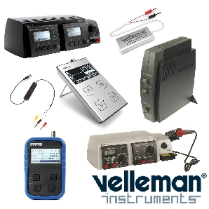
If I was buying again I'd look at Vellmman, as their function generator and scope can be automated to generate Bode (frequency response) plots.
 
Last edited:

BlueX

Well-Known Member
Joined
May 5, 2020
Messages
2,695
Reaction score
5,665
Location
Sweden
I'm completely comfortable with the scope and amp solidly earthed, power supplied via the house RCD. Rather I'd be uncomfortable with it any other way.
I use a usb Picoscope, I hardly ever power up my old analogue scope. It includes a basic function generator. It's nice having stuff displayed on a decent sized screen.
If I was buying again I'd look at Vellmman, as their function generator and scope can be automated to generate Bode (frequency response) plots.
You mean these?

 
Top