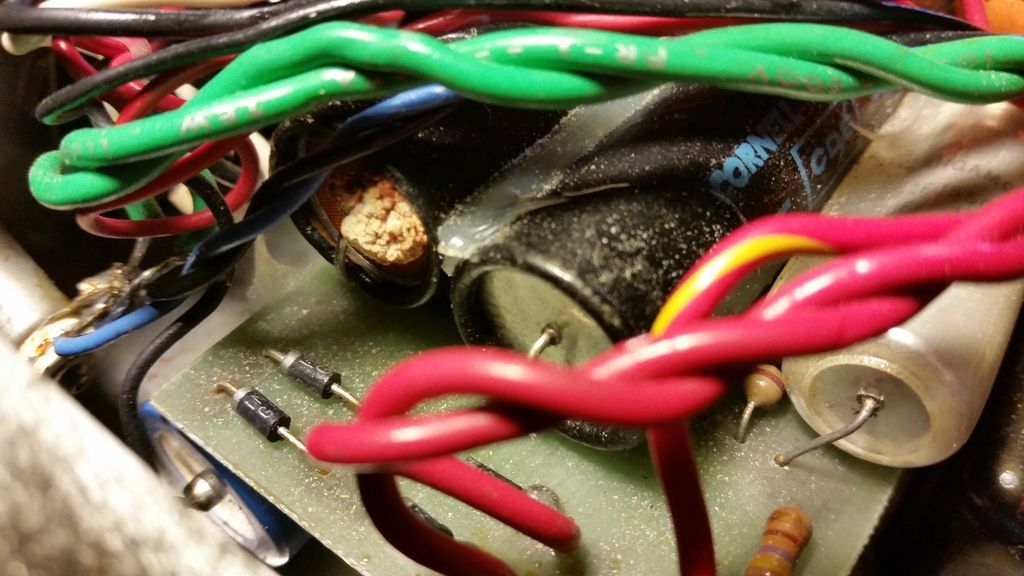
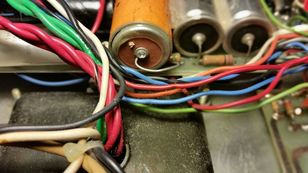
I am getting ready to order filter caps for an old amp. The power supply layout is quite different than what I am used to seeing in a 100W amp. There is no schematic available (none I could find) for this amp. It is a bit of a rare bird, built right here where I live somewhere around 1979/1980 going off some date codes I found on the filter caps.
The amp is a Mitchell Pro 100 and is a ballpark knock off of an early Mesa Mark series amp. It runs four 12AX7's, one is for the reverb. V1 V2 and half of V3 tube all share the last filter node. Not sure about the Mesa amp this is copying, but I would think Mesa has a more filter stages.
Anyway, the main question I have is the first section of the power supply and filtering. And would like opinions regarding if I should should alter it or if it is good to keep it as is.
The standby switch is after or downstream from the rectifier diodes circuit. This amp is using the same configuration as a 50W Marshall JCM800 era, as it has two diodes in series on each leg of the power transformer secondary HT. So, it goes from the HT legs -> rectifier diodes -> two 60uF 350 caps in series/150K resistor across each cap -> standby switch. Then on the downstream side of the standby switch or soldered to the outgoing or cold terminal of the switch, there is another filter cap 33uF 500V under the board. This is where I scratched my head as it is added to the first 30uF stage but only when amp is out of standby. The cap is different as well and maybe it was an after thought by Mr. Mitchell or a mod by a previous owner.
From the standby switch it goes to the output transformer primary center tap then to the choke that drops over 10V and measures 750 ohms. Never seen a choke measure that high in DC resistance. Has 20uF 600V cap for screens then a 5K dropper then 33uF 500V that feeds V4 phase inverter and goes to the reverb transformer and half of V3. Then 10K dropper then 33uF 500V is the last stage for half of V3 and V2 and V1.
I am going to order F & T caps. Will go with two 220uF 350V totem pole for that first stage. Would like opinions here on that standby switch configuration. Wondering if I should re-work that.
I am going to increase screen filtering to 47uF 500V F & T. From there I am going to look for some early Mesa Mark series schematics and see how they are laid out. Will be interesting to see how close this amp is to the Mesa, and I would like to make it a close copy.
Where the funkiness might end up is that this Mitchell has a built in 6 band EQ. The EQ circuit is an actual MXR EQ built into the amp LOL. I have not traced it out to see where it is at in the circuit yet. Funny as I have been considering looking into those switchable EQ circuits mesa uses. I love the EQ circuits on my Mesa amps DC-10 and Nomad 100.


