JohnH
Well-Known Member
Background
Passive attenuators are wired between the amp output and the speakers. Their function is to absorb most of the output power of the amp, feeding a smaller amount to the speaker itself. This allows the amp output stage to run at higher power, letting the glorious tone of a good valve output stage develop, but without excessive volume.
The attenuator must present a load to the amp that is similar to a speaker and also maintain the tone as volume is reduced. It needs a consistent tonal and dynamic response from low attenuation, down to sub-bedroom level. This is where the simplest designs can be inferior, and the best commercial designs get expensive.
With feedback and testing by others I think we have a reactive attenuator design that achieves this. This is an ongoing open-source project and for around $150, anyone with workshop skills and the ability to follow a circuit schematic can build this. I want to thank everyone who has built one of these or contributed to this thread, with a special thankyou to @Gene Ballzz who was the first to see the potential and has been a great source of insight and practical help for everyone.
An important point:
Anyone who builds these does so at their own risk, and takes responsibility for working out their own wiring for their own private, non-commercial use, and completing it safely
News: August 2024: The Fromel Lotus JohnH M2
Some very exciting news! For those who would like to buy one ready made instead of a DIY build, the attenuators are now being manufactured for sale by Fromel Electronics, initially based on the M2 design, the Fromel Lotus attenuators are available in all Ohms ratings from 2 to 16, with all output Ohms options. https://fromelelectronics.com/products/lotus-johnh-m2-simple-attenuator-60-watt
John Fromel ( @jfromel ) has added some terrific design flair and production expertise and we have worked together to resolve all details. I have one of them here. I'm really pleased with it. Its beautifully made and the circuit matches the design presented below, performing just as clearly and consistently at all settings.
Summary
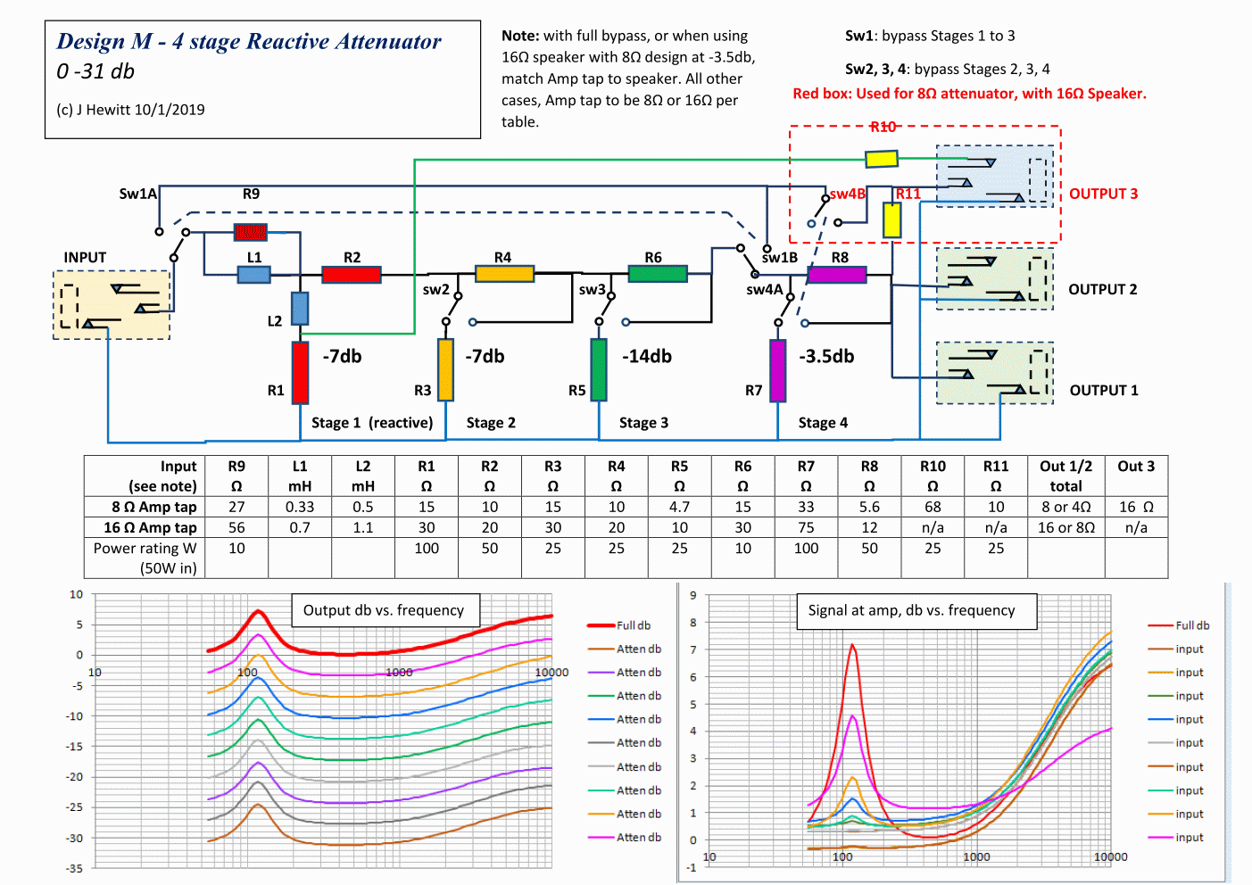
The main principles have been constant for several years. This 1st post shows the current basic design M2, and a few possible additions to it.

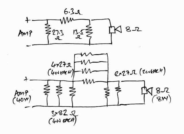
It must be matched to the output tap of the amp, eg 8 Ohm or 16 Ohms. Component values for both are given, which differ by a factor of two:.
There are 4 attenuation stages, engaged or bypassed by switches.
Stage 1 is the key reactive stage and includes an inductor coil. This stage on its own, reduces power by a factor of 5, or -7db, reducing a 50W amp to 10W. The inductor coil is configured so that the impedance presented to the amp is similar to that of a real speaker (values based on various Celestions), particularly how impedance rises with frequency.
After Stage 1, three more stages are provided. The design shown is based around additional -3.5db, -7db and -14db stages. By combining these switches in combination with Stage 1, reductions of up to -31.5db can be achieved in small, equal steps of -3.5db, at which point a 50W amp, at full power, is playing quietly at about 35mW.
4, 2.7 and 2 Ohm amps
The design can be adapted for lower Ohm amps, eg some old Fenders - here's a table. The output Ohms also reduce, eg, a 4 Ohm build will give outputs for 2, 4 and 8 Ohms from Out 4, Out 1&2 and Out 3 respectively.

1. For 2.7 Ohm option, Out 3 and 4 are for 4 and 2 Ohm cabs.
2. 7.5 Ohm is noted in a couple of places. 2x15 in parallel is a good option for this. Or 8 Ohm is OK if not 7.5.
3. 4 Ohm can be substituted with 3.9 Ohm
Edit 9/6/2024:
4. On 4 Ohm values, R7 changed from 18 to 15
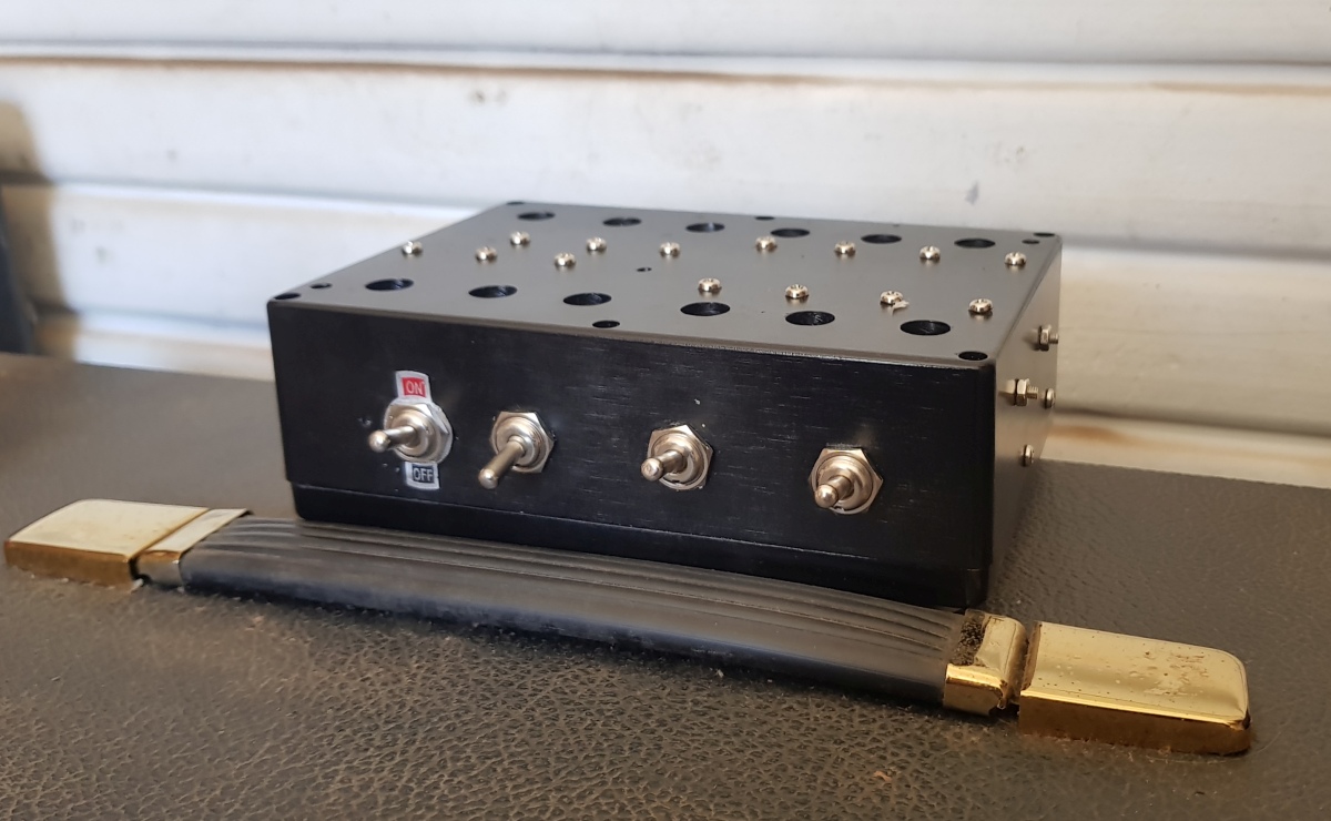
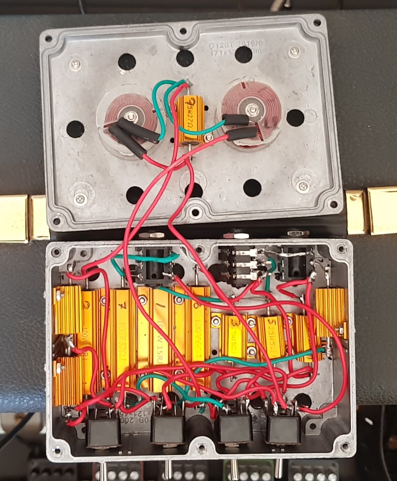
Construction layouts
On pages 111 and 112 are two construction layouts which may assist (designs are close to above, not identical though). I recommend studying the diagrams above to understand the connections and then adapt the layouts to suit your needs.
 www.marshallforum.com
www.marshallforum.com
www.marshallforum.com
Added features - 'Bells and Whistles' - Design M4
Further features can be added, discussed in the thread, such as bass resonance circuit, foot-switchable stage, variable input impedances, bypass switch etc.
For a schematic with most of these add-ons, go to Page 158, post 3146 from 19/11/2022.
www.marshallforum.com
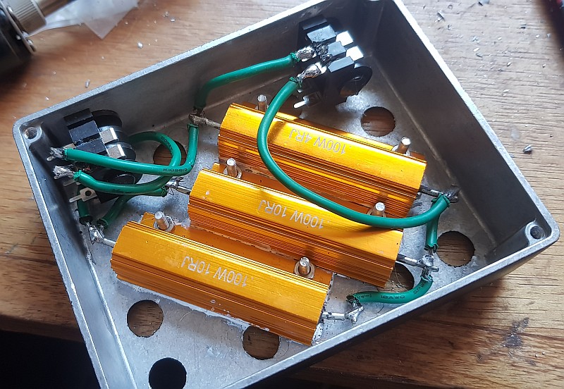
Component values and power ratings
The tables above show recommended power ratings for each resistor, based on up to 50W amps. The component ratings need to have a margin above the actual power. I use a factor of at least 3 for case-mounted aluminium resistors, bolted (with thermal grease) to a heavy metal chassis or heatsink, and a factor of 5 or more for air-cooled resistors. These values fit with the spec in the schematic diagram above and also allow for amp overdrive.
Here are Power Calculations, which tabulate the max power dissipated in each resistor. M2 and M4 designs are covered.
www.marshallforum.com
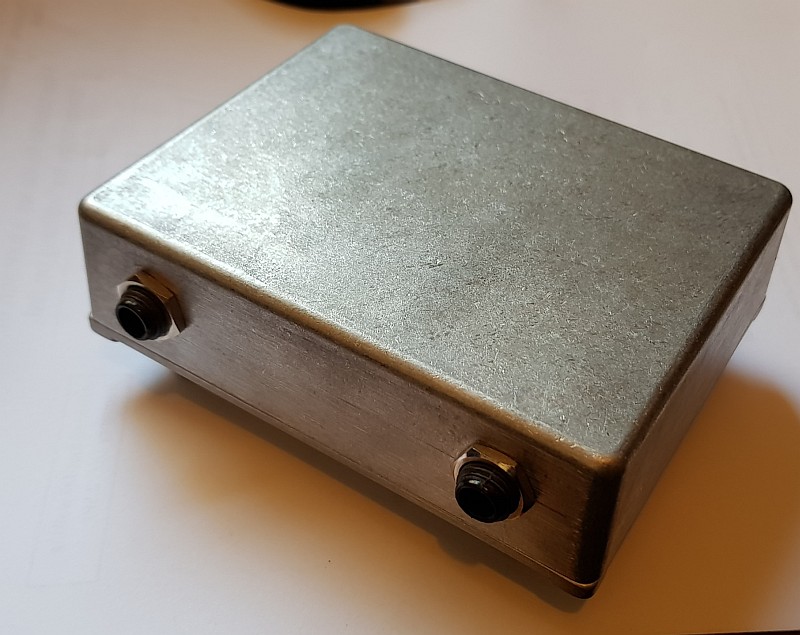
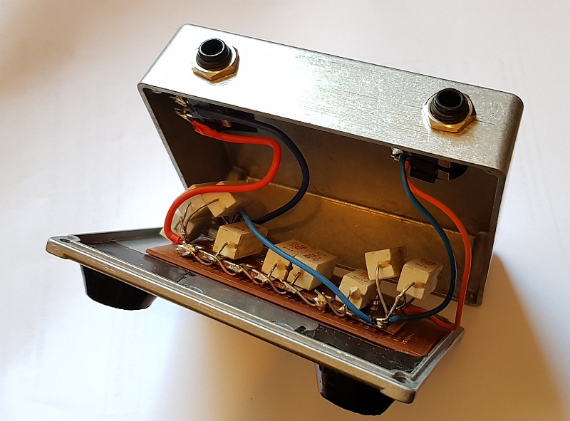
Hookup wire and also winding of air-cored inductors should be 18 gage for 50W builds, and this is also OK for a 100W build, if to the 16 Ohm values. For switches, use at least 5A rating (at 125Vac) for a 50W 8 Ohm build. The best jacks are plastic Cliff jacks, TRS (ie stereo type) which grip the plugs better than mono jacks.
Meter testing
It's important to check with a meter before connecting an amp. Plug in a speaker, plug a cord into the input but without amp, and measure resistance across the jack plug that would go to the amp.
For an 8 Ohm M2, it should be 7 to 10 ohms in every combination of switch settings, and x2 for a 16 Ohm build.
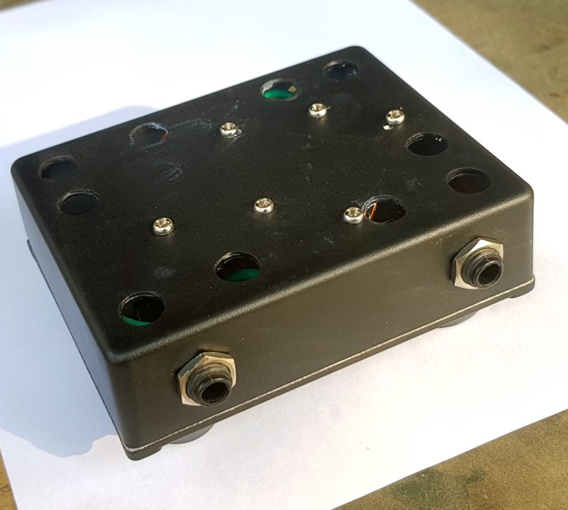
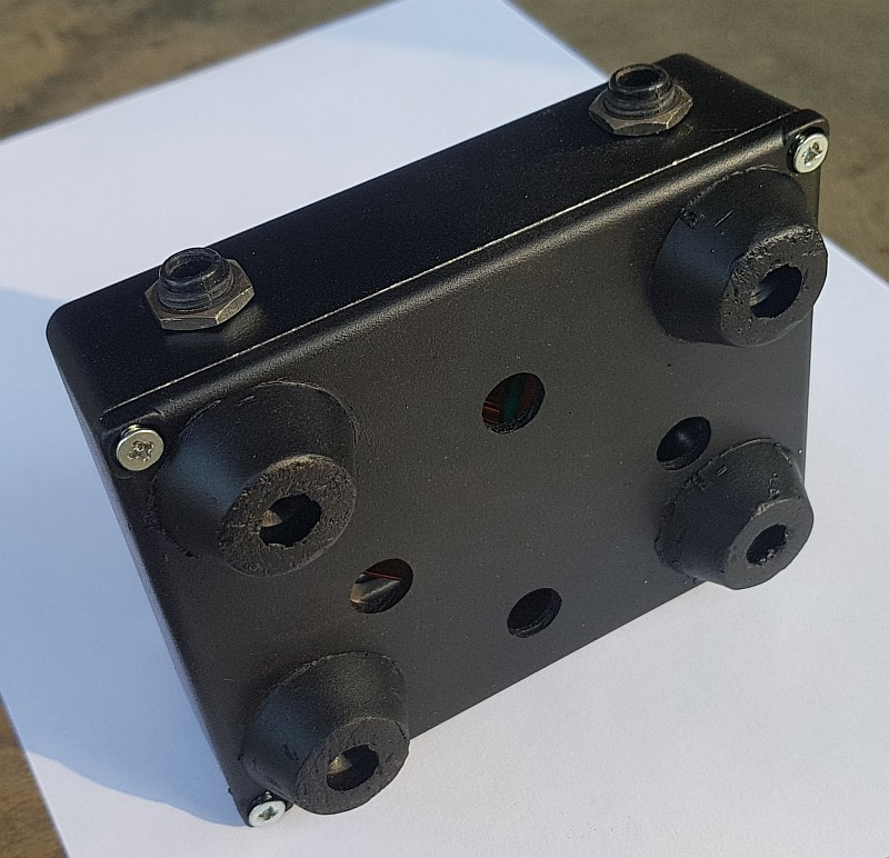
Cooling
With amps > 30W at high power, the unit will heat up as it dissipates power. A good size die-cast aluminium case is best. Once components are positioned, a number of additional large vent holes should be drilled, in the top and in the base, with feet to raise the base. This promotes good convective flow of air out through the top, replaced by cool air at the base. The best colours for cooling are dark. For amps more than 50W, a fan should be added
Mount the coil without using a ferrous bolt, with a few mm timber or plastic spacer off the case surface.
Thanks for reading. I suggest to read this post, look at the layouts and the most recent few pages, then make a post yourself and we'll be happy to discuss what would work best for you.
For nice collection of completed builds, see this thread:
www.marshallforum.com
Sound Samples
In the most post of 20/12/2022, @rowandg has presented sound samples stepping through attenuation settings, using an M2 built by @Gene Ballzz:
www.marshallforum.com
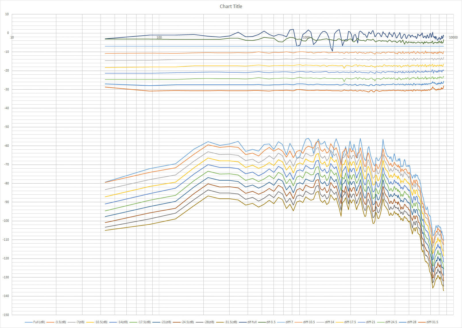
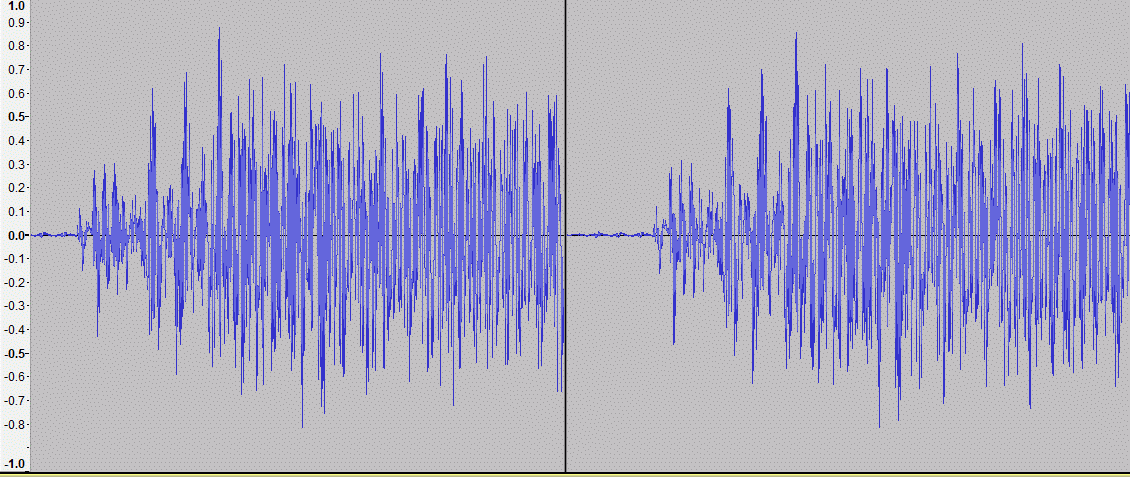
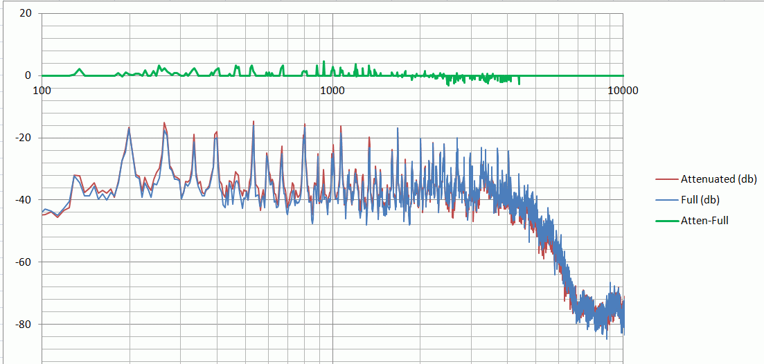
Frequency response plots
On page #169, @TomBallarino presents some very informative plots of measured frequency response from his M2, and also with bass resonance circuit from M3 and M4:
www.marshallforum.com
Prototype from 2019, Design M
To read about my first reactive design, with sounds samples and plots, please go to Post #3, linked here:
www.marshallforum.com
Passive attenuators are wired between the amp output and the speakers. Their function is to absorb most of the output power of the amp, feeding a smaller amount to the speaker itself. This allows the amp output stage to run at higher power, letting the glorious tone of a good valve output stage develop, but without excessive volume.
The attenuator must present a load to the amp that is similar to a speaker and also maintain the tone as volume is reduced. It needs a consistent tonal and dynamic response from low attenuation, down to sub-bedroom level. This is where the simplest designs can be inferior, and the best commercial designs get expensive.
With feedback and testing by others I think we have a reactive attenuator design that achieves this. This is an ongoing open-source project and for around $150, anyone with workshop skills and the ability to follow a circuit schematic can build this. I want to thank everyone who has built one of these or contributed to this thread, with a special thankyou to @Gene Ballzz who was the first to see the potential and has been a great source of insight and practical help for everyone.
An important point:
Anyone who builds these does so at their own risk, and takes responsibility for working out their own wiring for their own private, non-commercial use, and completing it safely
News: August 2024: The Fromel Lotus JohnH M2
Some very exciting news! For those who would like to buy one ready made instead of a DIY build, the attenuators are now being manufactured for sale by Fromel Electronics, initially based on the M2 design, the Fromel Lotus attenuators are available in all Ohms ratings from 2 to 16, with all output Ohms options. https://fromelelectronics.com/products/lotus-johnh-m2-simple-attenuator-60-watt
John Fromel ( @jfromel ) has added some terrific design flair and production expertise and we have worked together to resolve all details. I have one of them here. I'm really pleased with it. Its beautifully made and the circuit matches the design presented below, performing just as clearly and consistently at all settings.
Summary
The main principles have been constant for several years. This 1st post shows the current basic design M2, and a few possible additions to it.
It must be matched to the output tap of the amp, eg 8 Ohm or 16 Ohms. Component values for both are given, which differ by a factor of two:.
There are 4 attenuation stages, engaged or bypassed by switches.
Stage 1 is the key reactive stage and includes an inductor coil. This stage on its own, reduces power by a factor of 5, or -7db, reducing a 50W amp to 10W. The inductor coil is configured so that the impedance presented to the amp is similar to that of a real speaker (values based on various Celestions), particularly how impedance rises with frequency.
After Stage 1, three more stages are provided. The design shown is based around additional -3.5db, -7db and -14db stages. By combining these switches in combination with Stage 1, reductions of up to -31.5db can be achieved in small, equal steps of -3.5db, at which point a 50W amp, at full power, is playing quietly at about 35mW.
4, 2.7 and 2 Ohm amps
The design can be adapted for lower Ohm amps, eg some old Fenders - here's a table. The output Ohms also reduce, eg, a 4 Ohm build will give outputs for 2, 4 and 8 Ohms from Out 4, Out 1&2 and Out 3 respectively.
1. For 2.7 Ohm option, Out 3 and 4 are for 4 and 2 Ohm cabs.
2. 7.5 Ohm is noted in a couple of places. 2x15 in parallel is a good option for this. Or 8 Ohm is OK if not 7.5.
3. 4 Ohm can be substituted with 3.9 Ohm
Edit 9/6/2024:
4. On 4 Ohm values, R7 changed from 18 to 15
Construction layouts
On pages 111 and 112 are two construction layouts which may assist (designs are close to above, not identical though). I recommend studying the diagrams above to understand the connections and then adapt the layouts to suit your needs.
Simple Attenuators - Design And Testing
Wow this forum is amazing, im hoping to build a design for my amp, Im looking to have a headphone out as well as line out, becuase of the headphone out i want this section to have a cab sim, I was just wondering what was the point of m3 vs m2 does the m3 have a cab simulation as you keep...
www.marshallforum.com
Simple Attenuators - Design And Testing
Thanks @Markus Bender , that's very interesting indeed. Based on that, it looks to be just a simple resistive attenuator with some tone shaping. Once turned down, the amp sees almost none of that reactance. Here's a quote from their site: "We built into the RockCrusher a reactive load network...
www.marshallforum.com
Added features - 'Bells and Whistles' - Design M4
Further features can be added, discussed in the thread, such as bass resonance circuit, foot-switchable stage, variable input impedances, bypass switch etc.
For a schematic with most of these add-ons, go to Page 158, post 3146 from 19/11/2022.
Simple Attenuators - Design And Testing
Hi pietro, I reckon the case should not be grounded, and with the plastic Cliff jacks that we recommend, then the case is not in circuit at all. @JohnH , I have a "proposed" guess as to why we've encountered issues when the jacks get "grounded/connected together" through the metal enclosure...
www.marshallforum.com
Component values and power ratings
The tables above show recommended power ratings for each resistor, based on up to 50W amps. The component ratings need to have a margin above the actual power. I use a factor of at least 3 for case-mounted aluminium resistors, bolted (with thermal grease) to a heavy metal chassis or heatsink, and a factor of 5 or more for air-cooled resistors. These values fit with the spec in the schematic diagram above and also allow for amp overdrive.
Here are Power Calculations, which tabulate the max power dissipated in each resistor. M2 and M4 designs are covered.
Simple Attenuators - Design And Testing
hi @Dogs of Doom Thanks, and I apologize and didn't mean to ignore your good question! The way I think about these is: I start with the nominal power of the amp, and work out what steady-state share of that power would go into each component. Then to work out a spec rating, I first double it...
www.marshallforum.com
Hookup wire and also winding of air-cored inductors should be 18 gage for 50W builds, and this is also OK for a 100W build, if to the 16 Ohm values. For switches, use at least 5A rating (at 125Vac) for a 50W 8 Ohm build. The best jacks are plastic Cliff jacks, TRS (ie stereo type) which grip the plugs better than mono jacks.
Meter testing
It's important to check with a meter before connecting an amp. Plug in a speaker, plug a cord into the input but without amp, and measure resistance across the jack plug that would go to the amp.
For an 8 Ohm M2, it should be 7 to 10 ohms in every combination of switch settings, and x2 for a 16 Ohm build.
Cooling
With amps > 30W at high power, the unit will heat up as it dissipates power. A good size die-cast aluminium case is best. Once components are positioned, a number of additional large vent holes should be drilled, in the top and in the base, with feet to raise the base. This promotes good convective flow of air out through the top, replaced by cool air at the base. The best colours for cooling are dark. For amps more than 50W, a fan should be added
Mount the coil without using a ferrous bolt, with a few mm timber or plastic spacer off the case surface.
Thanks for reading. I suggest to read this post, look at the layouts and the most recent few pages, then make a post yourself and we'll be happy to discuss what would work best for you.
For nice collection of completed builds, see this thread:
Completed JohnH Attenuators?
Hey Fine Folks, The Simple Attenuator thread has become so lengthy that it is difficult to ascertain how many successfully completed builds there are of the fantastic @JohnH attenuator design. :thumbs: I'm starting this thread with the intention of showcasing all of these great builds. It is my...
www.marshallforum.com
Sound Samples
In the most post of 20/12/2022, @rowandg has presented sound samples stepping through attenuation settings, using an M2 built by @Gene Ballzz:
Completed JohnH Attenuators?
Now, these I would not be embarrassed to have sitting on top of my amp, onstage! Although, these two were built for a couple friends! My sincerest thanks to @DeluxeReverb for the inspiration to switch over to countersunk metric screws, for resistor mounting and to @Dblgun for the "gutter grate"...
www.marshallforum.com
Frequency response plots
On page #169, @TomBallarino presents some very informative plots of measured frequency response from his M2, and also with bass resonance circuit from M3 and M4:
Simple Attenuators - Design And Testing
Finally got round to building this. Thanks John H for your generosity in sharing the design. My previous experience with attenuators was with a Weber Mass and this easily surpasses it. I also have a Two Note Captor X. I find the Two Note to be a tad more transparent and has more presence but...
www.marshallforum.com
Prototype from 2019, Design M
To read about my first reactive design, with sounds samples and plots, please go to Post #3, linked here:
Simple Attenuators - Design And Testing
Background Passive attenuators are wired between the amp output and the speakers. Their function is to absorb most of the output power of the amp, feeding a smaller amount to the speaker itself. This allows the amp output stage to run at higher power, letting the glorious tone of a good valve...
www.marshallforum.com
Last edited: