Starting My First Guitar Amp Build . . . .

  • Thread starter RickyLee
  • Start date
  • This site may earn a commission from merchant affiliate links like Ebay, Amazon, and others.

RickyLee

Well-Known Member
VIP Member
Joined
May 22, 2010
Messages
10,295
Reaction score
3,709
Location
SoCal U.S.A.
Quite excited about this. Still have some decisions and options. Having options is good of course. I have an already loaded Plexi style/four input turret board. And then I have a turret board that needs components loaded, which was my original idea as I wanted to make some tweaks to the preamp layout as I loaded components on it. My tweaks were going to be either dual channel being able to switch between a stock Plexi channel and an added gain stage or hot rodded Marshall style. But the easier route is to obviously use the ready to go loaded board. And the other issue is that this blank board I just got does not match the chassis on the mounting holes. So that is more drilling of holes with that one. Probably going to start with the ready to go Plexi board and just build a Plexi to get the ball rolling. Make sure there's no bugs when finished, then implement ny tweaks from there as in adding another switchable gain stage or even better a second channel.

I am going with my shorter 100W small box chassis due to having a very sweet white JMP style head box to house it. But I am going to go with a 50W amp as I am excited about this new Classic Tone 50W power transformer 40-18095 I just got. I have a few 50W output transformers on hand with an old JCM800 era Drake and then I have had this Mercury Magnetics Plexi style 050-PLM. I just got my new Classic Tone 40-18058 3H 250mA chokes and then I also have a Mercury MC10H 10 Henry and a Mercury M-67C 2 Henry choke I could go with. Here is where I am looking for some feedback from our house Forum experts.

:D

I like the 10H choke because it has a higher DCR of well over 280 ohms. But I will be using the lower voltage HT secondary tap on the power transformer which will give me a loaded B+ of well under 400V. I will be building a 100W amp later and was thinking that 10H choke might be better suited for that to help lower the screen voltage on my power valves. I do not have to worry about screen voltage in this amp here with the low B+ under 400V. So that leaves the Mecury 2H M-67C with a DCR of 130 Ohms and the Classic Tone 3H with a DCR of 113 Ohms. I am figuring I will not hear an audible difference between these last two chokes. Any info and opinions are welcome on this subject. I am curious to the possible tonal change of running that 10H choke vs the 2H/3H choke?
 

RickyLee

Well-Known Member
VIP Member
Joined
May 22, 2010
Messages
10,295
Reaction score
3,709
Location
SoCal U.S.A.
Yeah, I was thinking about getting some pictures going for sure.
 

RickyLee

Well-Known Member
VIP Member
Joined
May 22, 2010
Messages
10,295
Reaction score
3,709
Location
SoCal U.S.A.
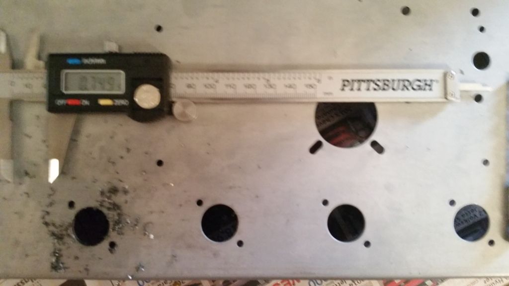
Well, first step was to add a fourth 12AX7 socket so I have options down the road. It was much easier than I thought it would be. I used my calipers to measure the locations of the other sockets and their .136" screw holes and spacing which is 2.5" apart. Laid it out and used a sharpie then scribed in my locations with the calipers into ther sharpie spots on the metal, then center punched the three locations. Then drilled the .136" holes first as well as opened the socket hole with that bit. Then used a .437" drill bit which is the biggest drill bit that would fit in my hand drill. Then opened up that socket hole with a step drill bit. Nothing to it.


Jaymz E

Well-Known Member
Joined
Sep 11, 2012
Messages
1,466
Reaction score
592
If I had the extra cash I'd build me a 50 watt Plexi. Seems like a good learning curve and something to do during the dreaded winter months coming up. Maybe I'll build a stomp box of some kind first.
Good Luck on your build Ricky and I'm looking forward to your build updates. A White 50 watt Plexi already sounds sweet!
 

RickyLee

Well-Known Member
VIP Member
Joined
May 22, 2010
Messages
10,295
Reaction score
3,709
Location
SoCal U.S.A.
I had to locate and drill the four output transformer mounting holes. Then I loaded in the four 12AX7 sockets and the two EL34 sockets. First Bummer was that extra 12AX7 socket hole I drilled ran off center just a touch with that step drill. Got the socket in there though. You probably can't tell from that picture though.

Second Bummer is I thought I had a good collection of stainless 4-40 hardware. I had the 4-40 nylock nuts but not the 4-40 X .375 phillips screws. Had to use some long brass screws for the time being. This chassis has the six holes for the 100W filter caps. I only installed four for now. I used that one location under the board for the last node. So my location of filter caps is not locked in yet.

And now the part of the build that I will probably not be too good at: The heater wiring.

:D

I am considering using the 5V 3A power transformer tap for DC heaters circuit on V1 - V3. V4 is my phase inverter and I am figuring you do not include the phase inverter in the DC heater string, correct? If you run DC heaters, do you still need to have twisted wires? Or just twisted wires for the phase inverter and power valves?

Then something else I have always wondered about is the orientation of the twist on the wires. Does that matter?

Then something else is coming to my memory as I thought I read somewhere there is shielded twisted pair wiring for making AC heaters even quieter. Any of you heard of this?
 

Jaymz E

Well-Known Member
Joined
Sep 11, 2012
Messages
1,466
Reaction score
592
Are you using a drill to twist the wire?
 

RickyLee

Well-Known Member
VIP Member
Joined
May 22, 2010
Messages
10,295
Reaction score
3,709
Location
SoCal U.S.A.
Are you using a drill to twist the wire?

I will use my drill. I am going to look at a few amp model schematics that use DC heaters and see what the circuit uses or needs. I have to see what I have for room as in where that circuit would reside. Might just put in a few turret strips and that could hold my DC heater circuit. I am figuring it will just be a rectifier, filter cap and a voltage regulator.

This is going to be a slow process as I have no work shop or much of a work space. Doing this in my kitchen right now. Then I have to put everything away, can't leave anything sitting around with the family staying here. Have to go play tomorrow then have to work OT Sunday LOL.

I guess it gives me time to think about a few decisions on the build anyway . . . .

:D
 

RiverRatt

Well-Known Member
VIP Member
Joined
May 2, 2008
Messages
8,738
Reaction score
3,252
Location
Between Memphis and Nashville
Ricky, I bought a set of Greenlee style knockout punches at Harbor Freight that do great for cutting holes for tube sockets. A step drill works but i could never get a neat looking cutout. I think the Harbor Freight punches were under $20 for the set, which is way less than a single Greenlee.
 

RickyLee

Well-Known Member
VIP Member
Joined
May 22, 2010
Messages
10,295
Reaction score
3,709
Location
SoCal U.S.A.
Ricky, I bought a set of Greenlee style knockout punches at Harbor Freight that do great for cutting holes for tube sockets. A step drill works but i could never get a neat looking cutout. I think the Harbor Freight punches were under $20 for the set, which is way less than a single Greenlee.

I will check into that for sure. I thought I had it whipped as I put that 3/4" hole in quick. But then when I went to put the tube socket in I noticed it drifted a bit. If I would have thought of it doing that I could have scribed the diameter lines in there as a guide, then probably would have noticed the drift and could have corrected/compensated it. But no problem as the socket went in. I am just a perfectionist and would probably get mad if it even went off center .005".

:D
 

RickyLee

Well-Known Member
VIP Member
Joined
May 22, 2010
Messages
10,295
Reaction score
3,709
Location
SoCal U.S.A.
Started reading into DC heaters and thinking it is a bad idea. This amp is not going to be a super high gainer anyway.
 

Jaymz E

Well-Known Member
Joined
Sep 11, 2012
Messages
1,466
Reaction score
592
I have an extra plug-in SS rectifier you can have if you decide to use a tube socket for your rectifier.
 

ampmadscientist

Well-Known Member
Joined
Jun 26, 2014
Messages
17,849
Reaction score
12,230
Location
Bio-Isolation Lock Down
Started reading into DC heaters and thinking it is a bad idea. This amp is not going to be a super high gainer anyway.

Choke calculator:
https://www.ampbooks.com/mobile/amplifier-calculators/LC-ripple-filter/calculator/

For example:
10mH choke, 50 uF filter (2X100 in series), Current 140ma at idle (35 per tube), 28 ohms DC resistance per Henry,
gives you: 49dB ripple attenuation, and a voltage drop of 3.92 volts.

3mH, same circuit: 38.5 dB ripple attenuation, voltage drop: 5.264 volts.
2mH: 34.9 dB attenuation, voltage drop 16.1 volts.

By matching Choke and filters, hum is minimized at a lower cost.

DC heaters for the first 2 preamp stages and the saturation stage (V2)
would be appropriate when the gain is very high.

No you do not include phase inverter.

But carefully laying out the AC filament wires to cancel filament BUZZ will work just as well.
(takes lots of patience) But, is better than 98% effective.

The Marshall factory filament layout...is not ideal. Rather noisy at best.

Fender filament style...audio horizontal, filament vertical...is much less noisy.

Twisting the filament wires...is not necessarily the quietest method.

I would build the Marshall with a Fender filament layout.
Sorry to upset you purists, I hate the BUZZING noise.

Photo:
Example of cancellation method for filaments.
I am deliberately feeding out of phase AC BUZZ into the V2 grid! (causing a cancellation of noise)
Producing a 98% reduction of filament BUZZ.
Wildly effective, and most time consuming.

Now you may call this: a hack...
but it works just as well as DC heaters. AND it's fully reversible back to stock.
 

Attachments

  • IMG_1768.jpg
    IMG_1768.jpg
    88.2 KB · Views: 39
Last edited:

Guitar-Rocker

Well-Known Member
Joined
Mar 5, 2012
Messages
3,250
Reaction score
3,167
Location
Estero, Florida formerly from Indianapolis
Ricky, Down near the bottom of this link from Valve Wizard is the way I twist and route my heater runs now, it works great, no noise (bottom right photo). It does take a bit to get used to doing it this way, but there are no wires that cross your heater run this way.

http://www.valvewizard.co.uk/heater.html

Also this build guide might be of assistance for ideas:

http://www.metroamp.com/downloads/50_WATT_KIT_INSTRUCTIONS.pdf


heater%20wiring_zpsa3h6y97f.jpg


finished%20inside%20RH_zpslpsdj4gn.jpg
 

m1989jmp

Active Member
Joined
Apr 24, 2014
Messages
922
Reaction score
153
I've done a bus style heater in my JCM/JMP build and will probably float it at some point.

It worked great, AC hum is audible only at very low volumes, past 3-4 on both volumes it's overpowered by thermal noise.
 

danman

Active Member
Joined
Apr 27, 2014
Messages
463
Reaction score
158
Location
Richmond, Va
If you need a complete hardware kit, with all of the proper size nuts and screws for the sockets and other components, Valvestorm sells complete kits for both the 50 and 100 watt amps. Nothing worse than being short a nut when you are busy assembling an amp.
 

RickyLee

Well-Known Member
VIP Member
Joined
May 22, 2010
Messages
10,295
Reaction score
3,709
Location
SoCal U.S.A.
So the direction of the twist for AC has no bearing on hum cancelation? I am seeing both counter clockwise and clockwise, but I thought I went with counter clockwise in the past workings for heater runs.

I tried looking into the subject last night and only found the twist orientation may help with keeping the wire put. I know that I have quite a few old Marshall amps that sure need a redo as AmpMad mentioned.

Also, elevated heaters sounds interesting. That might be something cool to try in this project.

Also, if I go with that loaded turret board, I can't officially call this my first build any more. I did not load up that board.

:D
 
Top