Blues 1911
New Member
- Joined
- Jul 16, 2022
- Messages
- 2
- Reaction score
- 3
Hello fellas, first post here.
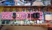
I've built myself a Marshall 10xxx series replica, with Heyboer transformers (Drake 1203-80-ML PT with 240V primary and tap for reduced voltage (80%) on the secondary, and Drake 1202-132 OT) and Larry Grounding. Mustard coupling caps and Murata ceramics, just like in the old specimens. The bright cap wasn't still installed when the picture was taken, I actually decided for a historically correct 100pf, even if 5000pf sounded incredible and delightfully crunchy.

I've used the 80% taps and 8,2K drop resistor.
Voltages looks pretty much correct on the preamp, but are quite low on the power tubes despite my very high wall AC (245V!). It also happens that B+ on the rectifier output is around 420V in the beginning, and after some minutes (even 20) it suddenly falls around 400V:
______V1____V2____V3_____V4 and other power tubes
Pin 1__191___169___208
Pin 2_______________23
Pin 3_1.44____1___________400
Pin 4_____________________392
Pin 5
Pin 6__185___291___213
Pin 7________169____26
Pin 8__1.44___170___40
Pin 9
I've read that B+ on vintage 10xxxs was around 480V, so using the 80% taps should give even less than 400V indeed. What I'm wondering is if, with the lower voltage, preamp voltages shouldn't be lower respect to what I'm measuring. I fear something's not right somewhere.
I have used the 80% taps because I was expecting indeed a higher B+ (500V+). I have later discovered that 10xxxs seem to have a way lower B+, even while stock, respect to JTM 45/100s and JTM100s.
Using 80% taps looked also sensible in a prospective of tube preservation, as the EHX I have on aren't supposed to tolerate high voltages very well (especially on the EL34s screens).
I'd wish to know (better from someone who has measured voltages on an original 10xxx) if a 400V B+ is what to expect using the 80% taps on Drake 1203-80-ML power transformer, or if it is due to some kind of issue I have on my project. WIth a 460-480V stock B+, using the 80% taps should give even less than 400V indeed. What I'm also wondering is if, with the lower voltage, preamp voltages shouldn't be lower respect to what I'm measuring.
The questions are:
1) Is the 460/480V B+ reported from the old schematics to be assumed as correct for vintage 10xxxs?
2) With the lower voltage taps (80%), preamp voltages shouldn't be lower respect to what I'm measuring?
3 Shouldn't I be worried using EHX EL34s and 12AX7s with the stock voltages?
Thanks for your attention!
I've built myself a Marshall 10xxx series replica, with Heyboer transformers (Drake 1203-80-ML PT with 240V primary and tap for reduced voltage (80%) on the secondary, and Drake 1202-132 OT) and Larry Grounding. Mustard coupling caps and Murata ceramics, just like in the old specimens. The bright cap wasn't still installed when the picture was taken, I actually decided for a historically correct 100pf, even if 5000pf sounded incredible and delightfully crunchy.

I've used the 80% taps and 8,2K drop resistor.
Voltages looks pretty much correct on the preamp, but are quite low on the power tubes despite my very high wall AC (245V!). It also happens that B+ on the rectifier output is around 420V in the beginning, and after some minutes (even 20) it suddenly falls around 400V:
______V1____V2____V3_____V4 and other power tubes
Pin 1__191___169___208
Pin 2_______________23
Pin 3_1.44____1___________400
Pin 4_____________________392
Pin 5
Pin 6__185___291___213
Pin 7________169____26
Pin 8__1.44___170___40
Pin 9
I've read that B+ on vintage 10xxxs was around 480V, so using the 80% taps should give even less than 400V indeed. What I'm wondering is if, with the lower voltage, preamp voltages shouldn't be lower respect to what I'm measuring. I fear something's not right somewhere.
I have used the 80% taps because I was expecting indeed a higher B+ (500V+). I have later discovered that 10xxxs seem to have a way lower B+, even while stock, respect to JTM 45/100s and JTM100s.
Using 80% taps looked also sensible in a prospective of tube preservation, as the EHX I have on aren't supposed to tolerate high voltages very well (especially on the EL34s screens).
I'd wish to know (better from someone who has measured voltages on an original 10xxx) if a 400V B+ is what to expect using the 80% taps on Drake 1203-80-ML power transformer, or if it is due to some kind of issue I have on my project. WIth a 460-480V stock B+, using the 80% taps should give even less than 400V indeed. What I'm also wondering is if, with the lower voltage, preamp voltages shouldn't be lower respect to what I'm measuring.
The questions are:
1) Is the 460/480V B+ reported from the old schematics to be assumed as correct for vintage 10xxxs?
2) With the lower voltage taps (80%), preamp voltages shouldn't be lower respect to what I'm measuring?
3 Shouldn't I be worried using EHX EL34s and 12AX7s with the stock voltages?
Thanks for your attention!

 and welcome to the forum
