1969 Marshall 50 unbalance bias

BlueX

Well-Known Member
Joined
May 5, 2020
Messages
2,658
Reaction score
5,609
Location
Sweden
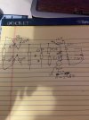
This is the schematics I use for my '69 1986 (JMP50). Note that this schematics shows standby switch before rectifier (AC switching), instead of after rectifier (DC switching).

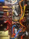
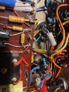
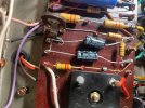
I need to look closer at the pictures, difficult to follow all red wires, and some are under board.

There are some dodgy looking solder joints here and there. I would go over those again.

M-U 1986 schematics.gif
 

Vpvalmus

Member
Joined
May 21, 2023
Messages
66
Reaction score
30
The thin red wire coming off the bottom of the stand by is going to the choke. I'm not sure it that's correct.
 

BlueX

Well-Known Member
Joined
May 5, 2020
Messages
2,658
Reaction score
5,609
Location
Sweden
The thin red wire coming off the bottom of the stand by is going to the choke. I'm not sure it that's correct.
Depends. Have you traced wires from the plus-sign on the rectifier block?

Looks like you've got DC switch (after rectifier). Then the wire should go to HT fuse, and from there to choke and to OT center tap. There should also be a filter cap (double can) connected in this section.

Maybe HT fuse is before standby switch

Looks like the bias feed (white wire) is connected right (to one of the wave symbols on the rectifier block).
 

Vpvalmus

Member
Joined
May 21, 2023
Messages
66
Reaction score
30
It appears the brown wire on the standby switch is the center tap. This test was with the el34s out.
I tested it with the choke disconnected ( it was soldered to the same point). CT to P3
V4 42.6
V5 44
Attached the choke
V4 43.6
V5 45.1
Checked the 220K to P3
V4 220K
V5 211.4
I went through almost all of the resistors and caps (except the .22 1000vI didn't take them out of circuit. The specs were close.
I'm leaning that there is an issue with the tube socket. It looks like a lot of residue or something is on the back. The pins look good and are tight.
I purchased some NOS Amphenol sockets. That will be my last attempt before it goes to the shop.
Any thoughts anything else? I could replace the .1 with .022?


mickeydg5

Well-Known Member
Joined
Sep 30, 2011
Messages
28,591
Reaction score
16,367
Location
The middle east of the united states of America
I have swapped the El 34s in the sockets and no change
V5 is red plating after 1-2 minutes

Measurements
V5
P5 on standby, -38v, power on -25v
P3 410v
P4 with the resistor 403v
V4
P5 on standby -38.9, on -35.5
P3 407
P4 with resistor 391
the bias pot appears to be set at the lowest point.

I tried the same with V3 out, no difference.
Can the choke make a difference? If I soldered the choke what is the measurement?
With this description I would look into power tube socket arcing or carbon shitzle causing the malfunctioning bias voltage to the grid.
Maybe, I do not know. It is worth a thought.
 

BlueX

Well-Known Member
Joined
May 5, 2020
Messages
2,658
Reaction score
5,609
Location
Sweden
I purchased some NOS Amphenol sockets. That will be my last attempt before it goes to the shop.
Any thoughts anything else? I could replace the .1 with .022?
I would wait for the new sockets and put them in before I did anything else. Plausible cause.
 

Vpvalmus

Member
Joined
May 21, 2023
Messages
66
Reaction score
30
Would you use Amphenol NOS ceramic or same NOS Amphenol that came in the Marshall?
 

BlueX

Well-Known Member
Joined
May 5, 2020
Messages
2,658
Reaction score
5,609
Location
Sweden
Would you use Amphenol NOS ceramic or same NOS Amphenol that came in the Marshall?
I think the preference is new sockets, instead of used, and well known brand sourced from reputable dealer.

I have no experience myself with Amphenol, but others commend them.
 

Vpvalmus

Member
Joined
May 21, 2023
Messages
66
Reaction score
30
Update. I replaced V5 socket and the runaway bias in V5 stopped. It was a conductive socket. I didn't replace v4. The issue I have is that the lowest I can adjust the bias is about 49-50mv. Plate 430. I tried different set of tubes. I measured the bias trim pot and it's 24K (lowest). the bias resistor is at 47K. Thoughts? Do you think V4 old socket could be effecting the bias adjustment? Attached is a pic of the conductive tube socket. Thanks,
 

Attachments

  • Tube socket.jpg
    Tube socket.jpg
    174.5 KB · Views: 11

Pete Farrington

Well-Known Member
Joined
Jan 18, 2021
Messages
3,217
Reaction score
4,246
Location
Staffordshire UK
. I didn't replace v4
It's made from the same materials and has been subject to the same conditions as its partner that's failed, so it seems remiss not to replace both?
It's not as if failed insulation here is inconsequential :rofl:

the bias resistor is at 47K
Feeding that there's a 15k resistor; what does that measure?
Feeding that there's a diode then 220k, then the white wire; what does that 220k measure?

I suspect your amp has that 'gold star stupid' standby arrangement. With that, standby deenergises the bias supply as well as the HT supply.
That should be simple to verify, ie lug 5 loses its negative voltage in standby.
If that's the case, I suggest not to use standby until the white wire is moved to a unswitched feed.
 

Spanngitter

Well-Known Member
Joined
Jan 22, 2019
Messages
515
Reaction score
563
Location
Upper Palatinate / Bavaria
Update. I replaced V5 socket and the runaway bias in V5 stopped.
Seems like this socket was soaked with some oily stuff (maybe cheap contact cleaner) causing resistance between pins.
There could be also cracks or arc marks but the picture is insufficiently detailed to determine that but I had this a few times already where these cracks did lead to socket internal arcing, leaving a carbon trace which acts like a resistor and deterioriating Bias....
 

BlueX

Well-Known Member
Joined
May 5, 2020
Messages
2,658
Reaction score
5,609
Location
Sweden
Update. I replaced V5 socket and the runaway bias in V5 stopped. It was a conductive socket. I didn't replace v4. The issue I have is that the lowest I can adjust the bias is about 49-50mv. Plate 430. I tried different set of tubes. I measured the bias trim pot and it's 24K (lowest). the bias resistor is at 47K. Thoughts? Do you think V4 old socket could be effecting the bias adjustment? Attached is a pic of the conductive tube socket. Thanks,
Good that you solved the main problem! Still, I would replace V4 as well. Same age probably.

Feeding that there's a 15k resistor; what does that measure?
Feeding that there's a diode then 220k, then the white wire; what does that 220k measure?

I suspect your amp has that 'gold star stupid' standby arrangement. With that, standby deenergises the bias supply as well as the HT supply.
That should be simple to verify, ie lug 5 loses its negative voltage in standby.
If that's the case, I suggest not to use standby until the white wire is moved to a unswitched feed.
Measuring the bias circuit resistors, as suggested, would be valuable.

If they measure as expected you could put in a pot with wider range (e.g. 100k instead of 50k) to see have much resistance you need to get the needed bias range. After that you might want to replace the 47k.
 

Vpvalmus

Member
Joined
May 21, 2023
Messages
66
Reaction score
30
the plot thickens. I change V4 socket and now the bias will only go down to 75 the old socket went to 50. Another strange issue is that in V4 with the old and new socket, the bias starts off at about a 100 and slowly comes down. The old socket was about 85 down to 50, new socket 100 down to 75. V5 slowly raises up to about 50. Also, I'm using the bias master. What could be the cause of that?
 

Attachments

  • Both new sockets.jpg
    Both new sockets.jpg
    146.6 KB · Views: 5

BlueX

Well-Known Member
Joined
May 5, 2020
Messages
2,658
Reaction score
5,609
Location
Sweden
Can you adjust to desired bias with the bias pot?

The bias probe can cause some problems. Another way (instead of the probe) is to solder a 1 Ohm resistor between p8 and chassis. I use 2 Watt rated (1R/2W). This resistor should be instead of the direct connection to ground.

Then you measure mV across that resistor. The mV reading gives you mA bias current (same value).

Did you measure all relevant resistors after you replaced the sockets (just in case of over-heating)? That would be all resistors connected to V4/5 (and the bias resistors mentioned above)?
 

Vpvalmus

Member
Joined
May 21, 2023
Messages
66
Reaction score
30
The bias adjustment is at it's lowest. I measured it and I am getting 0 to 24K. I did check the resistors, but I'll check again. Is the bias measurement for the 1ohm and pin 5? Should the bias start high and come down? If so, that's opposite of V5, which starts low and goes high. .
 

BlueX

Well-Known Member
Joined
May 5, 2020
Messages
2,658
Reaction score
5,609
Location
Sweden
The bias adjustment is at it's lowest. I measured it and I am getting 0 to 24K. I did check the resistors, but I'll check again. Is the bias measurement for the 1ohm and pin 5? Should the bias start high and come down? If so, that's opposite of V5, which starts low and goes high. .
To avoid confusion, could you list the following (with Unit of Measure)?
- Setting of bias pot
- Voltage at p5 for V4/5 (-V)
- Bias with the probe for V4/5 (mA or mV)

Do you have measurements with different settings for the bias pot? Please include, if so.
 

Vpvalmus

Member
Joined
May 21, 2023
Messages
66
Reaction score
30
the setting of the bias pot is at the max resistant at 24K. If I adj it, the bias goes up. all measurement is at max resistance.

For clarification, do I install the 1 ohm R between gd and pins 1 and 8 for the measurments?
Then, measure the bias from pin 5 on V4 and V5 with the gd side on the meter attached on the other side of the 1 ohm or gd to V4 and V5?
Even though they are NOS Amphenol sockets, I sprayed cleaner, not deoxide to remove some flux. Now V4 bias starts low and goes up v. starts high and goes down.
I'm getting about 40mv on the bias and then drifts up to over 60mv. Maybe there is a resistor failing after the voltage is applied. All the measurements are in spec when powered down. See attached chart.
Can I attach a resistor after the 47K where the wire is located. See Pic. If so, what value?
 

Attachments

  • 7.jpg
    7.jpg
    92.8 KB · Views: 5
  • 8.jpg
    8.jpg
    144 KB · Views: 5

dtier

Well-Known Member
Joined
Nov 3, 2021
Messages
485
Reaction score
589
Location
St Louis Mo
Can you adjust to desired bias with the bias pot?

The bias probe can cause some problems. Another way (instead of the probe) is to solder a 1 Ohm resistor between p8 and chassis. I use 2 Watt rated (1R/2W). This resistor should be instead of the direct connection to ground.

Then you measure mV across that resistor. The mV reading gives you mA bias current (same value).

Did you measure all relevant resistors after you replaced the sockets (just in case of over-heating)? That would be all resistors connected to V4/5 (and the bias resistors mentioned above)?
This ^^^^ The external bias probes external wiring can cause instability/oscillation on the 50 watters because they have no grid stopper resistors. Either install the 1 ohm bias resistors to check bias or install 5k6 grid stoppers on the tube sockets and check bias again.
 

BlueX

Well-Known Member
Joined
May 5, 2020
Messages
2,658
Reaction score
5,609
Location
Sweden
the setting of the bias pot is at the max resistant at 24K. If I adj it, the bias goes up. all measurement is at max resistance.

For clarification, do I install the 1 ohm R between gd and pins 1 and 8 for the measurments?
Then, measure the bias from pin 5 on V4 and V5 with the gd side on the meter attached on the other side of the 1 ohm or gd to V4 and V5?
Even though they are NOS Amphenol sockets, I sprayed cleaner, not deoxide to remove some flux. Now V4 bias starts low and goes up v. starts high and goes down.
I'm getting about 40mv on the bias and then drifts up to over 60mv. Maybe there is a resistor failing after the voltage is applied. All the measurements are in spec when powered down. See attached chart.
Can I attach a resistor after the 47K where the wire is located. See Pic. If so, what value?
You could, temporarily, replace the bias pot (seems to be 25k) with a 50k or 100k pot. This will allow you to test if more resistance will bring the bias down to the desired value.

Yes, "bias probe resistor" (1 Ohm) is installed between p8 and chassis/ground. p1 and p8 should still be connected. If you install this resistor you should no longer use the Bias Master.

With the bias probe resistor in place you measure voltage across that resistor (between p8 and chassis/ground). This will give you the bias current. If you measure for example 35 mV then the bias current is 35 mA (because A = V with 1 Ohm resistance).

Voltage between p5 and ground is what "drives" the bias current, and it's something different.
 

Vpvalmus

Member
Joined
May 21, 2023
Messages
66
Reaction score
30
Ok, I added the 1r resistors. I'm getting about 45 to 50mv across the 1R. I have switched different tubes and about the same result. The trim pot is at the highest resistance of 24K. Does something have to be out of spec in the bias circuit or is this sometimes normal? Should I take some voltage measurements at different points in the bias circuit? Also, the choke has one wire going to the standby switch with the brown ct wire and the other black wire is attached to the yellow wire to the screen. See pic. Not sure it that's correct or could that be causing an issue. I don't have a 50 or 100K trim pot, could I add a 25K resistor in front of the trim pot? Thanks
 

Attachments

  • 9.jpg
    9.jpg
    802.3 KB · Views: 2

Latest posts


Top