1971 JMP Marshall need more info

  • Thread starter neskor
  • Start date
  • This site may earn a commission from merchant affiliate links like Ebay, Amazon, and others.

neskor

Member
Joined
Nov 22, 2020
Messages
30
Reaction score
33
Hi.
I have a great offer for this amp.
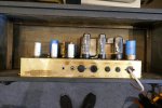
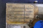
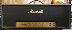
Seller told me this is a 1971 JMP 50W but not sure.
Can you please tell me is this '71 or later JMP 50W.
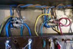
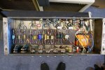
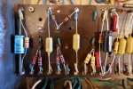
Looking the PCB it looks like 1986 bass amp.
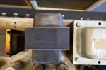
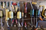
Power transformer is changed and some other parts on the PCB.
Also cabinet is not from that era?
 

Attachments

  • chcw3bn4aknl6zsnkxcy.jpg
    chcw3bn4aknl6zsnkxcy.jpg
    220.5 KB · Views: 58
  • oxcamy02jcwaqnrkafrw.jpg
    oxcamy02jcwaqnrkafrw.jpg
    252.8 KB · Views: 59
  • uw98fzyfzsifpx0qqdcg.jpg
    uw98fzyfzsifpx0qqdcg.jpg
    193 KB · Views: 62
  • aucomxdjyt37tz3fpfij.jpg
    aucomxdjyt37tz3fpfij.jpg
    217.6 KB · Views: 53
  • axwtukn7aqhtngg9qrca.jpg
    axwtukn7aqhtngg9qrca.jpg
    149.5 KB · Views: 51
  • b3kryjkp9ganzagwgnbd.jpg
    b3kryjkp9ganzagwgnbd.jpg
    155.3 KB · Views: 50
  • bgidqwwrmuzjj7f0qwii.jpg
    bgidqwwrmuzjj7f0qwii.jpg
    168.2 KB · Views: 50
  • mpelwvkoqsobunzjy9ac.jpg
    mpelwvkoqsobunzjy9ac.jpg
    202.9 KB · Views: 50
  • rbljmfdvpxyuhgka2rau.jpg
    rbljmfdvpxyuhgka2rau.jpg
    156.1 KB · Views: 45
  • ylx0ao7tmm0soxz0w1bb.jpg
    ylx0ao7tmm0soxz0w1bb.jpg
    127.4 KB · Views: 48

TAZIN

Well-Known Member
Joined
Mar 18, 2013
Messages
1,183
Reaction score
1,346
I agree with the early November 1970 (within the first two week) build date. A lot of changes circuit wise so I hope the asking price is reflective of this. @neikeel this one is all yours!
 

TAZIN

Well-Known Member
Joined
Mar 18, 2013
Messages
1,183
Reaction score
1,346
I'll have a go at this one...It looks like a whacked out single channel JTM45 type circuit. The valve rectifier, reduced mains & preamp filtering along with increased B+ voltages as a result of eliminating two of the 10K/1w dropping resistors is what points toward a JTM45 type circuit. The "whacked out" part is the apparent single channel coupled with a 2K7/320uF cathode arrangement for the first preamp valve and a cathode bypass cap for the second preamp valve. Changes & replaced parts:

As mentioned earlier, the PT has been changed and the head cabinet is not original.
Channel 1 (bright channel) appears to be disconnected by way of no input wire at V1 grid.
V1 cathode (Channel 2) has a 320uF cap (normal) but has a 2k7 resistor instead of the normal 820-ohm.
For V2a the cathode resistor is a replacement, and someone added a fairly large (250uF?) bypass cap.
The 100K resistor for V2b cathode is also a replacement.
The preamp filter cap (normally a 50+50uF/450v) has been changed to a single 10uF/450v. Additionally, one of the 10K/1w B+ dropping resistors was eliminated for the preamp section.
The output coupling caps for the phase inverter have been swapped out of two 0.047uF? caps.
Another 10K/1w B+ dropping resistor was eliminated which will allow more voltage to the preamp section.
The bias circuit has new caps and an added trimmer pot for adjustment. Not sure why they performed the update in this fashion...Perhaps the new PT supplies a weird voltage?
Both front panel switches have been replaced along with the Indicator light.
The Presence pot is a replacement.
Added Volume pot bypass caps for both channels (1 &2).
The one speaker jack is a replacement as is Mains Fuse holder.
The Mains/power cord is a replacement.
As mentioned earlier, the diode rectification circuit has been replaced by a valve rectifier.
Added 1K/5w Screen/grid resistors on the output valve sockets.
Also added 100-ohm resistors on the output sockets.

This amp would not require too many components in order to return it to "stock" model 1987 (Lead) specs but it would require a fair amount of labor time-wise.
 
Last edited:

neskor

Member
Joined
Nov 22, 2020
Messages
30
Reaction score
33
Perfect!
Thank you Tazin.
I don't see that V1 grid is disconnected, check attached picture.
Also there is a small cap on V2 between grid and plate.
 

Attachments

  • q8dctv0rfdy793kcbwuf.jpg
    q8dctv0rfdy793kcbwuf.jpg
    363.2 KB · Views: 11

neikeel

Well-Known Member
Joined
Feb 12, 2014
Messages
8,452
Reaction score
9,605
Sorry late to party.
Importantly started as lead amp (see angle of the 68k grids on V1a and unused turret for split cathode)
Someone swapped slope resistor for cc 56k (vs 33k). Guess treble cap swapped too. The output couplers would be 22nF but looks like 39 or 47nF for that in between range (bass spec being 100nF).
Board material is typical for late 69 to early 71.
The rest you can see and was pointed out by Tazin
I like these sorts of quick resto projects but I’d go back to stock.
 

AndyD

Well-Known Member
Joined
Sep 13, 2018
Messages
1,210
Reaction score
1,476
Location
UK
FYI the headshell is from a ‘74 ish Lead and Bass model 1964. I have this amp.
 

TAZIN

Well-Known Member
Joined
Mar 18, 2013
Messages
1,183
Reaction score
1,346
Perfect!
Thank you Tazin.
I don't see that V1 grid is disconnected, check attached picture.
Also there is a small cap on V2 between grid and plate.
I couldn't make out that jumper wire before so, it is a shared cathode setup for both channels.
 

TAZIN

Well-Known Member
Joined
Mar 18, 2013
Messages
1,183
Reaction score
1,346
Sorry late to party.
Importantly started as lead amp (see angle of the 68k grids on V1a and unused turret for split cathode)
Someone swapped slope resistor for cc 56k (vs 33k). Guess treble cap swapped too. The output couplers would be 22nF but looks like 39 or 47nF for that in between range (bass spec being 100nF).
Board material is typical for late 69 to early 71.
The rest you can see and was pointed out by Tazin
I like these sorts of quick resto projects but I’d go back to stock.
I overlooked the open turret and the angle on the two 68K grid resistors...Good catch.
 

Latest posts


Top