1980s Marshall 2000 Lead 250 Watt Head

  • Thread starter scozz
  • Start date
  • This site may earn a commission from merchant affiliate links like Ebay, Amazon, and others.

Marshallhead

Well-Known Member
Joined
Jun 3, 2009
Messages
1,459
Reaction score
657
Ok.... It turns out, you CANNOT use a simple two button SPST switch. When you do channel adding, you need something like what I am showing in the attached photo. I have tested this theory with jumper wires - it works.

View attachment 148369
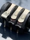
I built a footswitch using two conductor and screen mic cable, and a double throw single pole footswitch, with the screen connected to the centre. That allowed selection of either channel A or B , and if I recall there’s a small voltage across the tip and screen / ring and screen that supports having an indicator led on the footswitch pedal. E.g when one side of the switch was closed, the other had enough voltage across the poles I ran a single LED to signify gain channel engaged.

It didn’t allow selection of both channels together, but to my ears the amp sounded awful with both channels mixed anyway - the non master channel over powered the gain channel when I picked or strummed hard and sounded weird.
 

TomCarlos

Member
Joined
Mar 8, 2024
Messages
28
Reaction score
36
After resolving the problem of the Mix Input Jack, which must be Tip=NO, Ring and Sleeve=NC, I did some testing for the Footswitch.

I took a Stereo cable but stripped the ends off one end. So you insert the plug into the Footswitch Jack (and of course your guitar plugged into the Mix Input Jack). Now then.... if the two wires on the cable are NOT connected to anything, both A and B are on. If you take the wire of the Ring and connect that to the ground lead, B will shut off and A will be on. And Vice Versa, Connect the Tip to ground but leave the Ring open - only B will be on. So the diagram I posted seems to be working correctly. I have tested using jumper cables but will built a box soon. I also plan the add a battery and LEDs to the footswitch so you can see A only, B, only, or Both. Stay tuned !!!
 

Attachments

  • Cliff Jack.jpg
    Cliff Jack.jpg
    15.7 KB · Views: 1

Dogs of Doom

~~~ Moderator ~~~
Staff Member
Joined
Aug 2, 2012
Messages
32,926
Reaction score
55,528
Location
Los Angeles
I remember, in another old thread (good luck finding it, I couldn't), I posted this video, of Marshallhead's amp & he chimed in on that one. I wish I could find the thread. Here's the vid:


so you know he's the real deal...

There was an ad, one time, someone selling one, that had great images inside & out, w/ a great description. All the images were on photobucket though & the images were jacked up...

These amp's are rare birds. The reason I always ask for images, is simply for archival & discussion. Photobucket ruined many a forum, in that regard, when they switched to paid subscriptions...
 

TomCarlos

Member
Joined
Mar 8, 2024
Messages
28
Reaction score
36
DOD
I remember, in another old thread (good luck finding it, I couldn't), I posted this video, of Marshallhead's amp & he chimed in on that one. I wish I could find the thread. Here's the vid:


so you know he's the real deal...

There was an ad, one time, someone selling one, that had great images inside & out, w/ a great description. All the images were on photobucket though & the images were jacked up...

These amp's are rare birds. The reason I always ask for images, is simply for archival & discussion. Photobucket ruined many a forum, in that regard, when they switched to paid subscriptions..


DoD ... Once I finish my repairs and have the amp "working the way it is supposed to work", I will take photos of the guts, front, and back. I believe the amp I have in front of me is a Revision 1. It had multiple 68K grid resistors on the PC board. Revision 2 and Revision three calls for jumpers and moving the 68K resistors directly to the tubes V1 and V5. The amp also started off with using KT77 power tubes in Revision 1 then moved to 6550s. Rev 3 then made some changes to the circuitry around the power tubes. Here are the schematics.

Series_2000_Output_Revision_1.JPGSeries_2000_Preamp_Revision_1.JPGSeries_2000_Output_Revision_2.gifSeries_2000_Preamp_Revision_2.gifSeries_2000_Output_Revision_3.jpgSeries_2000_Preamp_Revision_3.jpg
 

Marshallhead

Well-Known Member
Joined
Jun 3, 2009
Messages
1,459
Reaction score
657
Here you go - you prompted me to dig my amp out of storage and get you some pics. That mix input is indeed a modified stereo TRS jack, with the tip set to close, rather than open, when a jack is inserted.

Photos in next post.
 

Marshallhead

Well-Known Member
Joined
Jun 3, 2009
Messages
1,459
Reaction score
657
is that original? or one you installed?

I notice it says Neutrik brand. It might be an idea to ask them, & that would explain why Cliff doesn't have the jack anywhere to be found...

does it have a parts # on it?

It was in the amp when I got it years ago, and you’ll see it’s fitted using flying leads rather than solder pins through the PCB.

No idea if it’s OEM or not, but it looks like it’s simply a regular TRS jack and the tip static piece has simple been pushed upwards, so it sits above rather than below its corresponding connection from the other side of the jack. The solder tag therefore appears shorter than usual too.
 

Marshallhead

Well-Known Member
Joined
Jun 3, 2009
Messages
1,459
Reaction score
657
By the way, don’t ask me to pull it out of its box again for more pics and questions, I already spent ages pulling it out the store and putting it back 😂
 

TomCarlos

Member
Joined
Mar 8, 2024
Messages
28
Reaction score
36
By the way, don’t ask me to pull it out of its box again for more pics and questions, I already spent ages pulling it out the store and putting it back 😂
No, I won't !! The next round of photos, schematics, footswitch wiring, etc will be on me. Once I get the Mix Input jack installed and footswitch rewired, I will be posting several photos. And thank you!!
 

Marshallhead

Well-Known Member
Joined
Jun 3, 2009
Messages
1,459
Reaction score
657
No, I won't !! The next round of photos, schematics, footswitch wiring, etc will be on me. Once I get the Mix Input jack installed and footswitch rewired, I will be posting several photos. And thank you!!
No worries! Mine hasn’t been powered up in a while, so will be getting a filter capacitor service before I hook it up again.
 

TomCarlos

Member
Joined
Mar 8, 2024
Messages
28
Reaction score
36
Ok.... as promised, here are some photos of the "guts." Please visit the sister thread titled Marshall JCM 800 Series 2000 235w amp, Mix A&B Input Jack.

This amp has been modified and I would say it has some Revision 2 changes and then changes to the output tubes.

On the preamp, the 68K grid resistors have been removed and I added a 68K directly connected to the Grid of V1 and V5.

On the output, the amp is wired up like Rev 2 BUT... someone installed KT88 tubes AND a 250 Ohm Cathode resistor that connects to each string of output tubes. Please don't ask me to explain this. You can visit the following post on the Music Electronics Forum site for that discussion - https://music-electronics-forum.com...996160-using-kt88-tubes-in-lieu-of-6550-tubes


Front.JPG Back.JPG IMG_4840.JPG Preamp Board.JPG Preamps Board 2.JPG Bias Board.JPG Inputs.JPG Relays.JPGPower Tubes.JPG Output Section.jpg
 

TomCarlos

Member
Joined
Mar 8, 2024
Messages
28
Reaction score
36
Forum Members

I am doing some testing on this amp before calling my friend to come over and have a listen. So far, the fabricated Mix Input jack is working well. The modified footswitch is also working well.

Talking with my friend today, he mentioned to me that compared to his other Marshall Amp, the Volume control on Channel B seems to have a different sweet spot compared to his other Marshall amp (that has a Gain and Volume control). When I say "sweet spot", I am talking about how far up you turn the knob before it gets loud!! And I just noticed something on the Revision 3 circuit. For VR11, Marshall went from using a 1K Log pot to a 5K linear pot. So if I am looking at this correctly, we have a voltage divider with R48.

Stupid question perhaps, but other than touch and feel or a sweet spot, would a 5K pot allow for more signal to pass compared to a 1K pot? At some point, as you turn that 5K pot it will have the equivalence to 1K?

I am trying to find a simple way to explain this - to my friend and to myself !!

VR11.JPG
 

anitoli

Well-Known Member
Joined
Jul 9, 2011
Messages
12,335
Reaction score
21,310
Location
Lewiston, Maine U.S.A.
Think the response has less to do with the pot value rather the taper is changed. A log pot will "stack up" differently than a linear taper will. This will change where the volume begins to really come on.
 

RadioAD5GB

Member
Joined
Dec 20, 2021
Messages
56
Reaction score
61
Location
Brighton, Tennessee
I've been toying with that circuit as the basis for another custom build. I'd need to get up close and personal with one though to be sure. 3 or 4 100W JCM800 full stacks (2 or 3 heads just piggybacked off of the "master" might be more to my liking sound-wise but I don't know. Heck, I would almost never be in a venue that would be able to use that power unless it's a large theater or outdoor gig. Then we just rent what we don't have. Heck, most of owners and sound techs in the places I play in just cringe when they see me wheeling in that 1960B and my customized Mojotone 2204 clone. I've usually got the AC15 just in case they try to throw me out LOL!
 
Last edited:

Latest posts


Top