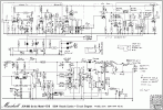
1982 JCM800 2205 is driving me nuts

Jason Patrick

New Member
Joined
Sep 21, 2024
Messages
4
Reaction score
2
Who has experience with working on these? This is an early one without the chip and I’m not to familiar with them and I’m fixing up a friends that sounded like crap cause the tubes were dead. I Cleaned the pots, installed new tubes, cleaned jacks, the normal procedures. Now it roars BUT, the volumes interactions are weird. The boost volume really affects the normal channel even with the boost off. I hear that this is an issue with these and is small potatoes for what I’m really trying to figure out. At certain settings of the volumes and gain, I’m getting a very starved fuzz pedal sound with like a ring modulator gated envelope type sound. When I play the guitar when it’s doing it, you really have to dig in to get a note to pop out. I noticed there are spots depending on how you tweek the gain and normal Chan volume where the volume drops out like there is high frequency oscillation going on. Lead dress is spot on, I did the chopstick poke poke, all components are in spec. I’m unfamiliar with amps using transistors tho, so I’m wondering could it be one of them? I can get great tone and crunch out of it but it just bothers me that I feel something is not right regardless. Oh and voltages seem to be golden. So, is this how these are with the diode clipping? I feel that’s where the problem may be. I usually fix old fender amps so this is a new one for me!
Thanks all!
 
Last edited:

TassieViking

Well-Known Member
Joined
Jun 20, 2021
Messages
254
Reaction score
266
Location
Under Downunder Where The Devils Roam At Night
You have me confused, diode clipping in a 2205 ???
There are only 2 transistors in the amp, one turns the channel LED on / off, the other one mutes the reverb signal.
There is one IC that is used to change channels and turn reverb on / off with the foot switch.
The main signal should be all tube as far as I know.
 

Attachments

  • jcm800_splitch_50w_2205.pdf
    141 KB · Views: 13

Jason Patrick

New Member
Joined
Sep 21, 2024
Messages
4
Reaction score
2
You have me confused, diode clipping in a 2205 ???
There are only 2 transistors in the amp, one turns the channel LED on / off, the other one mutes the reverb signal.
There is one IC that is used to change channels and turn reverb on / off with the foot switch.
The main signal should be all tube as far as I know.
this is an early one. No IC. Def more the two transistors in this. And yeah as far as I’ve read, diode clipping. Couple different schematics floating around. Think they changed this circuit three times
 

Attachments

  • IMG_1552.gif
    IMG_1552.gif
    176 KB · Views: 14

Gunner64

Well-Known Member
Gold Supporting Member
Joined
Nov 16, 2013
Messages
9,189
Reaction score
15,582
Location
Midwest, USA
I had a 2205 that behaved similar. It had at least one broken connection where the pot lugs are attached to the pcb.

The way you have to wrangle the pcb out puts stress on the pot lugs, not to mention the pcb itself is partially suspended by the pots. I reflowed all the lug to pcb connections and the problem was solved.

I suspected the gain pot, but did them all.

Not saying this is your issue, but it was mine, and is something to consider.
 

LyseFar

Well-Known Member
Joined
Jun 26, 2018
Messages
448
Reaction score
831
I restored a 89 2210 (the 100 w version) some time ago. It was very noisy and troublesome. I re-did all grounding, full cap job, internal electrolytics also.
What I also found that these has a weak impedance selector that actually had internal bad connection due to oxidation and dirt. After a cleanup the amp and the full service it sounds killer.
The interaction between the channels (channel bleeding) is by design to mimic the 4-holers way to blend the channels.
Remember these split channel amps were new territory for Marshall and they did some weird choices.
I still have the amp and I like it. Easy to dial in and fun to play.
Here is my service “log”.
 
Last edited:

Jason Patrick

New Member
Joined
Sep 21, 2024
Messages
4
Reaction score
2
I had a 2205 that behaved similar. It had at least one broken connection where the pot lugs are attached to the pcb.

The way you have to wrangle the pcb out puts stress on the pot lugs, not to mention the pcb itself is partially suspended by the pots. I reflowed all the lug to pcb connections and the problem was solved.

I suspected the gain pot, but did them all.

Not saying this is your issue, but it was mine, and is something to consider.
good to know, I read about that so I took the board out and all looked good under close inspection but I’ll go back and reflow.
 

Jethro Rocker

Well-Known Member
Joined
Mar 11, 2011
Messages
12,292
Reaction score
21,951
Location
Saskatoon, Canada
You have me confused, diode clipping in a 2205 ???
There are only 2 transistors in the amp, one turns the channel LED on / off, the other one mutes the reverb signal.
There is one IC that is used to change channels and turn reverb on / off with the foot switch.
The main signal should be all tube as far as I know.
I don't overly read schematics but I see more than a couple diodes here. That series had diode clipping as far as I know. All of them.
 

Tatzmann

Well-Known Member
Joined
Nov 8, 2021
Messages
2,549
Reaction score
4,438
The interaction between the channels (channel bleeding) is by design to mimic the 4-holers way to blend the channels.
Don't take it personal, but this is total nonsense.

The chiefdesigner, or head of the pack at that time is just not the greatest tube amp designer. He was trained on solid state.

Time and time again after the 800 splitchannel models we could see the whacky circuits he choose to put out. Some were just whacky (*Model2000/800-2chnl./900) others were plain faulty (*JCM2000 anyone?).
 

Purgasound

Rocker, Roller
Gold Supporting Member
Joined
Jan 9, 2009
Messages
4,683
Reaction score
2,629
Location
Central Virginia
I don't overly read schematics but I see more than a couple diodes here. That series had diode clipping as far as I know. All of them.
Yeah, I don't know what drives someone to come into threads to post nonsense like that and then include the schematic that shows the diode clipping circuit clear as day. Insert eye roll here...
 

LyseFar

Well-Known Member
Joined
Jun 26, 2018
Messages
448
Reaction score
831
Don't take it personal, but this is total nonsense.

The chiefdesigner, or head of the pack at that time is just not the greatest tube amp designer. He was trained on solid state.

Time and time again after the 800 splitchannel models we could see the whacky circuits he choose to put out. Some were just whacky (*Model2000/800-2chnl./900) others were plain faulty (*JCM2000 anyone?).
:)
Yeah. I know Wikipedia isn’t the most realisable source - but not the only place I’ve seen it. I was also told by a tech sometime.. Quote wiki
“……This is one of the reasons why many players prefer the early JCM 800 Models 2203/2204 to the 2205/2210, as they are considered to be more organic sounding without the added diode clipping.However, the 2210 and 2205 models were built with a channel bleed, which would let the "clean" channel bleed over into the lead channel if the channel volume is turned to about 7-10. With the right settings, this can create a plexi-style distortion which is great for hard and Punkrock.…..”.

Maybe total nonsense maybe not.

As I write in my post also. Marshall were om new territory… and made mistakes.
 
Last edited:

Piotr

New Member
Joined
Sep 19, 2019
Messages
1
Reaction score
1
In my opinion, the influence of diodes on the signal is overestimated. Personally, I really like diodes in the signal. Especially in lead tone. People complain about the diodes and then they plug the SD-1 between the guitar and the amplifier, which is one big semiconductor. Believe your ears, not myths.
 

rixmixnfix

New Member
Joined
Sep 17, 2024
Messages
1
Reaction score
1
I'm new here, so please excuse any duplications. I have been fixing Marshalls since the early 70's and many have parasitic oscillation problems. From Plexies through JCM 900s, I always redo all grounds. I replace the black small internal toothed washers with new cad plated ones after wire brushing all contact points and add a drop of Deoxit. Also, add 3/8 " IT washers to every pot, brush the front panel contact points and Deoxit. Next, shorten all grid wired as much as possible, both preamp, phase inverter, and output tube grid wires. Then replace the phase inverter plate to plate ceramic cap with the same value silver mica cap. It's alot of effort, but worth it. Balancing values of the bias, phase inverter, and output tube grid resistors with carbon comps also helps. Use matched output tubes.
I've done this to many dozens of amps and always brings smiles.
 

Pete Farrington

Well-Known Member
Joined
Jan 18, 2021
Messages
3,220
Reaction score
4,249
Location
Staffordshire UK
You have me confused, diode clipping in a 2205 ???
In the 1987 totally redesigned 2205 / 2210 schematic that you attached, I think the silicon diode clipping network is formed by W005 and D6.

Regarding the topic of diode clipping, it's worth bearing in mind that the forward biased control grid of the receiving type valves we use forms a diode clipper. See 1.14: Grid Current Clipping on p19 of http://www.valvewizard.co.uk/Common_Gain_Stage.pdf
 

Purgasound

Rocker, Roller
Gold Supporting Member
Joined
Jan 9, 2009
Messages
4,683
Reaction score
2,629
Location
Central Virginia
:)
Yeah. I know Wikipedia isn’t the most realisable source - but not the only place I’ve seen it. I was also told by a tech sometime.. Quote wiki
“……This is one of the reasons why many players prefer the early JCM 800 Models 2203/2204 to the 2205/2210, as they are considered to be more organic sounding without the added diode clipping.However, the 2210 and 2205 models were built with a channel bleed, which would let the "clean" channel bleed over into the lead channel if the channel volume is turned to about 7-10. With the right settings, this can create a plexi-style distortion which is great for hard and Punkrock.…..”.

Maybe total nonsense maybe not.

As I write in my post also. Marshall were om new territory… and made mistakes.
Total nonsense. Since wikipedia can be edited by anyone, I just went on there and deleted that entire paragraph. It's poorly, written, conjecture, misinformed, speculative and it's someone's opinion presented as facts.
They also call them "dual channel" amps when Marshall exclusively refers to them as "split channel".
Channel bleed is not described as a feature in any owners manual and it's clear by the design this was not intended. 100% this is a flaw, not a feature.
 

LyseFar

Well-Known Member
Joined
Jun 26, 2018
Messages
448
Reaction score
831
Total nonsense. Since wikipedia can be edited by anyone, I just went on there and deleted that entire paragraph. It's poorly, written, conjecture, misinformed, speculative and it's someone's opinion presented as facts.
They also call them "dual channel" amps when Marshall exclusively refers to them as "split channel".
Channel bleed is not described as a feature in any owners manual and it's clear by the design this was not intended. 100% this is a flaw, not a feature.
👍
It is more a channel mix I guess…only when using the dirty channel and turns the clean channel volume up. The clean mixes with the dirt. Not the other way around.
Anyways… the truth is out there… somewhere.
Well I bought my 2210 most of sentimental reasons as my first tube amp was the combo version (4211) I had from new in the mid 80’s…
I mostly play my 2203’s or my 1959 these days.
 
Last edited:
Joined
May 2, 2020
Messages
72
Reaction score
90
Looking at the schematic it looks to me like the 4 transistors are used for switching (gain and reverb.) When they turn on they ground out signal at the locations they're in the circuit. I'd start by checking them i.e. by pulling them out of the circuit(s) and using the diode checker on my DMM to make sure their good. Pay attention to where the collector, base, and emitter are on the board so you can replace them in the correct location.
 
Top