TassieViking
Well-Known Member
- Joined
- Jun 20, 2021
- Messages
- 258
- Reaction score
- 271
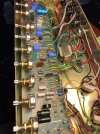
The transistors in the Normal and Boost channels are like switches that connects the signal to ground, they are meant to kill the signal by shorting it out.
When the transistor switch on and conduct its like throwing a switch in those circuits.
Replace the BC184 transistor in the the channel that bleeds through and it should fix that problem.
From memory the IC used in later amps in the switching circuit is just full of transistors, nothing else.
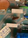
The 4 - 1N4007 diodes at the end of the boost channel might be there for clipping, but I have seen diodes in other amps like that and they are used purely to make sure the signal is not to high.
They might be there for a max signal limit and not for clipping, hard to tell unless checking with a CRO.
When the transistor switch on and conduct its like throwing a switch in those circuits.
Replace the BC184 transistor in the the channel that bleeds through and it should fix that problem.
From memory the IC used in later amps in the switching circuit is just full of transistors, nothing else.
The 4 - 1N4007 diodes at the end of the boost channel might be there for clipping, but I have seen diodes in other amps like that and they are used purely to make sure the signal is not to high.
They might be there for a max signal limit and not for clipping, hard to tell unless checking with a CRO.