2205 2210 Mods Thread!

  • Thread starter RickyLee
  • Start date
  • This site may earn a commission from merchant affiliate links like Ebay, Amazon, and others.

RickyLee

Well-Known Member
VIP Member
Joined
May 22, 2010
Messages
10,295
Reaction score
3,709
Location
SoCal U.S.A.
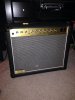
I'm thinking it would be a good idea to install the presence control on my 4210.

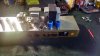
I can see the spot where the resistor is that I'd need to replace with a pot - but I'll have to put the pot on the back as there's no space on the combo front panel.

Ricky, do I need to use shielded wire to connect to the pot?

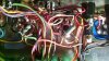
I think you can do the presence circuit without shielded wire. I have done it from the back a few times with no added noise. Just be careful where you route your wires.
 

RickyLee

Well-Known Member
VIP Member
Joined
May 22, 2010
Messages
10,295
Reaction score
3,709
Location
SoCal U.S.A.
The most obvious thing is the cathode bypass cap on V1A.
On my schematic, C2 is .47 uF.
It won't pass low frequencies. It's a high pass filter.
This will make the amp sound harsh in the high frequencies, because there is almost no bass to start with.
Replace that C2 with 2.2 uF or 4.7 uF or larger. This will cause the amp to finally pass bass. The + of the cap connects to the cathode. The - of the cap connects to ground. The cap should be rated 25 volts or more.

After you fix that problem, the low frequencies will be much better.
The highs and the lows will be balanced much better. The bass EQ will work much better.

AND if you want to try different values, and see the result, before modifying the amp, use THIS:
Cathode Bypass Capacitor Calculator

Now back to the input question.
The .047 cap on the input will block DC from entering the preamp. It will attenuate the low frequencies.
This CAN be bypassed. However, the cap should be replaced with resistors.
There should be a 33K - 68 K series resistor between the input jack and the first preamp tube. You don't need the capacitor.
I am replacing this .047 cap with a 33K resistor, that's all folks.

If you don't use the resistor, the input will be noisy, and distort too much (muddy sounding) from being overloaded with signal... The guitar should not be hooked directly to this tube, without a resistor in series.

Now, one more thing about high frequency harshness.
You can remove the "bright cap" C4, 100pf from the first volume control VR1.

My '88 2205 is actually quite tubby on the low end response. I have to run the Boost channel Bass quite low. Though a bigger V1A bypass cap would help the Normal channel.
I split the channels to have their own first gain stage on my 4210. So then I was able to put a bigger bypass cap for the Normal channel and I left the .47uF for the Boost channel.

I had also put a 56K grid resistor directly on the V1A socket for the input as well. That one I had to do quite a few years back as I was picking up radio stations at a particular bar I was playing at LOL.
 

vinceB

Active Member
Joined
Mar 22, 2013
Messages
223
Reaction score
48
Location
illinois
My '88 2205 is actually quite tubby on the low end response. I have to run the Boost channel Bass quite low. Though a bigger V1A bypass cap would help the Normal channel.
I split the channels to have their own first gain stage on my 4210. So then I was able to put a bigger bypass cap for the Normal channel and I left the .47uF for the Boost channel.

I had also put a 56K grid resistor directly on the V1A socket for the input as well. That one I had to do quite a few years back as I was picking up radio stations at a particular bar I was playing at LOL.

I hope you guys are still following this thread because I have a couple of questions. What will it do to the Normal channel if I increase the value of C2 and add bypass caps to V2a and b? What value would I want to start with there? Also, what does D1 do and what would happen soundwise if I put a bypass cap there?
 

vinceB

Active Member
Joined
Mar 22, 2013
Messages
223
Reaction score
48
Location
illinois
attachment.php


This is how she's looking in her new clothes:hbang:
 

Attachments

  • 10258047_10203004816335136_7191030473214657924_n.jpg
    10258047_10203004816335136_7191030473214657924_n.jpg
    78.5 KB · Views: 157

doverlane

New Member
Joined
Oct 24, 2014
Messages
105
Reaction score
102
Location
Chicago
This is a great thread!!!

Keep it up guys...

I just changed my filter caps and screen grid resistors.

Sounds great now...totally cleaned up the noise issue.
 

Attachments

  • IMG_20141031_155850273_HDR.jpg
    IMG_20141031_155850273_HDR.jpg
    98.6 KB · Views: 34
  • IMG_20141031_155915764.jpg
    IMG_20141031_155915764.jpg
    102.9 KB · Views: 38

RickyLee

Well-Known Member
VIP Member
Joined
May 22, 2010
Messages
10,295
Reaction score
3,709
Location
SoCal U.S.A.
I hope you guys are still following this thread because I have a couple of questions. What will it do to the Normal channel if I increase the value of C2 and add bypass caps to V2a and b? What value would I want to start with there? Also, what does D1 do and what would happen soundwise if I put a bypass cap there?

Sorry I did not see this way back when you posted it. I think you did already figure this stuff out?

Anyway, I am remembering you already increased that C2 and liked it.

As for that D1? That diode is passing all frequencies for that gain stage. Putting a cap in parallel with it will not do anything. That stage has quite a bit of gain and gives the Split Channel Boost channel (later version) most of its brutal distortion character.
 

vinceB

Active Member
Joined
Mar 22, 2013
Messages
223
Reaction score
48
Location
illinois
Sorry I did not see this way back when you posted it. I think you did already figure this stuff out?

Anyway, I am remembering you already increased that C2 and liked it.

As for that D1? That diode is passing all frequencies for that gain stage. Putting a cap in parallel with it will not do anything. That stage has quite a bit of gain and gives the Split Channel Boost channel (later version) most of its brutal distortion character.

Initially I was happy with everything I did but something in the boost channel just isn't sounding right. I replaced D1 with a cap and at first I liked it but now that I've been playing it a lot I'm not sure. I need to understand the clipping circuit better because instead of trying to get rid of it perhaps it can be adjusted to suit what I am looking for. I don't quite understand what the rectifier with D6 across it does exactly. That whole mess between V1a and V3a is very confusing to my basic grasp of this.:scratch:
 

mickeydg5

Well-Known Member
Joined
Sep 30, 2011
Messages
28,591
Reaction score
16,367
Location
The middle east of the united states of America
D6 across DB1 creates a 3 diode per side clipping circuit dropping about 3VAC.

D1 paralled with R3 at V1b provides higher current/gain when the input signal is at 1VAC or above. This helps signal passing through the clipping and tone circuits that follow.
A capacitor would be more frequency dependent and always working whereas the diode only turns on at forward bias. If you use both the capacitor may aid at low levels but as soon as 1V is attained the diode takes over.
 

vinceB

Active Member
Joined
Mar 22, 2013
Messages
223
Reaction score
48
Location
illinois
D6 across DB1 creates a 3 diode per side clipping circuit dropping about 3VAC.

D1 paralled with R3 at V1b provides higher current/gain when the input signal is at 1VAC or above. This helps signal passing through the clipping and tone circuits that follow.
A capacitor would be more frequency dependent and always working whereas the diode only turns on at forward bias. If you use both the capacitor may aid at low levels but as soon as 1V is attained the diode takes over.

thanks for this info. Is there a way for me to tweak the character of the clipping circuit to warm it up a little? Is this an asymmetric clipping circuit or symmetric? :coffee:
 

vinceB

Active Member
Joined
Mar 22, 2013
Messages
223
Reaction score
48
Location
illinois
Since I made the changes to the Normal channel a 12AX7 will no longer work in v2. The 12AU7 is the only tube that will work now. What could I have done that would cause that? It doesn't sound bad at all I was just curious what the 12AX7 would sound like with the changes and the answer is, it doesn't.:scratch:
 

mickeydg5

Well-Known Member
Joined
Sep 30, 2011
Messages
28,591
Reaction score
16,367
Location
The middle east of the united states of America
thanks for this info. Is there a way for me to tweak the character of the clipping circuit to warm it up a little? Is this an asymmetric clipping circuit or symmetric? :coffee:
I am not sure what you mean by "warm". Describe that.

The clipping circuit is symmetrical, three diodes each way.
If you want asymmetrical, 3 diode - 2 diode, then short any two adjacent legs of the bridge rectifier W005.
If you want two diodes each way then short D6.
If you want 2 diode - 1 diode then short D6 and any two adjacent legs of the bridge rectifier.
If you want some Germanium flavor try two diodes arranged properly and paralleled on one side of the bridge, like the "+" side.

You can also try anything from .003uF (3nF) or smaller across the bridge rectifier from top to grounded side to see about smoothing the clipping.
 

RickyLee

Well-Known Member
VIP Member
Joined
May 22, 2010
Messages
10,295
Reaction score
3,709
Location
SoCal U.S.A.
Since I made the changes to the Normal channel a 12AX7 will no longer work in v2. The 12AU7 is the only tube that will work now. What could I have done that would cause that? It doesn't sound bad at all I was just curious what the 12AX7 would sound like with the changes and the answer is, it doesn't.:scratch:

All you did on the Clean channel V2 was add cathode bypass caps on each triode of V2, correct? I did something similar and had no issues.

What is the problem? No sound coming through or is it overloading, oscillating?

Something to keep in mind regarding the Clean/Normal channel. It is already capable of quite a bit of signal or volume in its stock state. So adding those caps might have been a bit too much. Try removing one or the other and see what happens.
 

vinceB

Active Member
Joined
Mar 22, 2013
Messages
223
Reaction score
48
Location
illinois
All you did on the Clean channel V2 was add cathode bypass caps on each triode of V2, correct? I did something similar and had no issues.

What is the problem? No sound coming through or is it overloading, oscillating?

It depends on what tube I use. sometimes there is just very little output and another tube will be real quiet but if I hit the strings a little harder it gets loud and sounds awful then immediately cuts off. I tried several tubes and moved them around so I don't think it's the tube. It all started because I really dug the tone but I have this real old RCA 12AX7 I wanted to try in V2 just for the heck of it. I think I will try removing one of those bypass caps. Now I want to mess with the rectifier as well. I swore I was done but I can't stop messing. As far as "warm" I think I mean darker and smoother. A little less tube screamer and a little more sd-1 if you will.
 

mickeydg5

Well-Known Member
Joined
Sep 30, 2011
Messages
28,591
Reaction score
16,367
Location
The middle east of the united states of America
It depends on what tube I use. sometimes there is just very little output and another tube will be real quiet but if I hit the strings a little harder it gets loud and sounds awful then immediately cuts off. I tried several tubes and moved them around so I don't think it's the tube. It all started because I really dug the tone but I have this real old RCA 12AX7 I wanted to try in V2 just for the heck of it. I think I will try removing one of those bypass caps. Now I want to mess with the rectifier as well. I swore I was done but I can't stop messing. As far as "warm" I think I mean darker and smoother. A little less tube screamer and a little more sd-1 if you will.

Adding a normal value cathode bypass capacitor should not halt any of those preamp tubes from working. What tube position)s) and what value capacitor(s) is being used?

If you want more midrange and low frequency in the BOOST channel then bump up the value of coupling capacitor C7 .002uF. Try piggybacking a capacitor for additional capacitance value there to see what you might like; anything from another .002uF to maybe .02uF.
 

mickeydg5

Well-Known Member
Joined
Sep 30, 2011
Messages
28,591
Reaction score
16,367
Location
The middle east of the united states of America
I did not want to speculate causes but if it were sitting there with a 10A fuse and got hit with something from the utility supply then I would suspect the PT first but that is not saying that a multitude of other things may have been affected with that sort of amperage.

I am not saying this is what happened but is a possibility.
 

vinceB

Active Member
Joined
Mar 22, 2013
Messages
223
Reaction score
48
Location
illinois
Adding a normal value cathode bypass capacitor should not halt any of those preamp tubes from working. What tube position)s) and what value capacitor(s) is being used?

If you want more midrange and low frequency in the BOOST channel then bump up the value of coupling capacitor C7 .002uF. Try piggybacking a capacitor for additional capacitance value there to see what you might like; anything from another .002uF to maybe .02uF.

I used a 10uF bypass cap on V2A and a 22uF on V2B. Its weird because it works with the 12AU7 it's just a little thin. The boost channel appears to be unaffected no matter what I use in V2.
 
Top