3210 mods help?

  • Thread starter fitz
  • Start date
  • This site may earn a commission from merchant affiliate links like Ebay, Amazon, and others.

fitz

Well-Known Yinzer
Gold Supporting Member
Joined
Apr 7, 2020
Messages
10,953
Reaction score
32,045
Location
SW PA USA
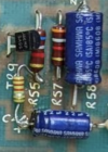
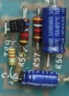
Comparing a new-to-me 3210 that I picked up today to one I had a few years ago.
Had a blown mains fuse, so I'm waiting on some fuses before I can power it up.
Not sure if these are good or bad things or cause for a blown fuse - any input appreciated.

Pics are all new one with something added vs. the old one I had.

D5 n.JPG D5 o.JPG

D9-R30 n.JPG D9-R30 o.JPG

R48 n.JPG R48 o.JPG

R55-C44 n.JPG R55-C44 o.JPG

Schematic attached.
 

Attachments

  • Marshall-3210-Schematic.pdf
    281.1 KB · Views: 9
  • 3210-iss7.gif
    3210-iss7.gif
    789.4 KB · Views: 14

PelliX

Well-Known Member
Joined
Jun 16, 2020
Messages
7,225
Reaction score
14,685
Pics are all new one with something added vs. the old one I had.

D5 n.JPG
D5 o.JPG

Hmm, looks like someone was trying to replace R73... maybe a trace got damaged? Same pretty much for the capacitor in paralllel with R48 (replacing C61?). The resistor from C44 to R55 is a bit dodgy, not sure what someone was thinking there, exactly.

The resistor between D9 and R30 doesn't immediately make much sense to me. Might come back to that after more coffee. Hmmm.

Whoever had a hack at this made a bit of a pig's ear of the thing. How about the rest of the board, does it look damage-free and otherwise unmolested? Any burn marks or such?
 

Jon Snell

Well-Known Member
Joined
Apr 12, 2020
Messages
854
Reaction score
1,227
Location
Jurassic Coast, England. Great Britain.
Someone with no idea has been playing!
Take a look at the issue 7 schematic, (updated) and things don't look good at all.
If there had been an issue with production, Marshall wouldn't bodge it, like this.
 

Attachments

  • Screenshot 2024-08-28 at 07.29.51.png
    Screenshot 2024-08-28 at 07.29.51.png
    267.6 KB · Views: 4
  • Screenshot 2024-08-28 at 07.24.50.png
    Screenshot 2024-08-28 at 07.24.50.png
    263.9 KB · Views: 4

PelliX

Well-Known Member
Joined
Jun 16, 2020
Messages
7,225
Reaction score
14,685
Awesome, Fitz. Looks pretty OK, no blowholes in the IC's, no disastrous failures. Not sure about the T3A label there, the board states T2A for 120V operation and a 1A for 220 and up. I don't see it needing the full 3A - certainly time delayed, but I assume you'll bring it up with an LBL, right? You mentioned ordering fuses, what did you buy? It wouldn't hurt to meter out the rectifier while you wait. I think you have a DMM with a diode test mode, right? Worst case, DC resistance should tell you pretty much all you need to know about its condition. Maybe check your primary and second winding resistance, too.

I'd be inclined to lift the legs on the 'extra parts', though I doubt that "C61 surrogate" is the main problem here.
 

fitz

Well-Known Yinzer
Gold Supporting Member
Joined
Apr 7, 2020
Messages
10,953
Reaction score
32,045
Location
SW PA USA
Not sure about the T3A label there, the board states T2A for 120V operation and a 1A for 220 and up. I don't see it needing the full 3A - certainly time delayed
I ordered T3A - that was also the value on the blown one.
I assume you'll bring it up with an LBL, right?
Don't have one, but I could probably cobble one together with some basic instructions.
I think there was a thread here that I bookmarked.

Got a pack of 10 fuses inbound.
I was going to start off with the "put a fuse in and see if it blows" method first... :D
It wouldn't hurt to meter out the rectifier while you wait. I think you have a DMM with a diode test mode, right? Worst case, DC resistance should tell you pretty much all you need to know about its condition.
Um, I have a DMM, and then you started to assume I understand what you're talking about...
 

fitz

Well-Known Yinzer
Gold Supporting Member
Joined
Apr 7, 2020
Messages
10,953
Reaction score
32,045
Location
SW PA USA
No diode test on my DMM. (Southwire 10030S)
I do know what/where the rectifier is, but not what to test.
Maybe check your primary and second winding resistance, too.
Also not sure what to look for here.
 

PelliX

Well-Known Member
Joined
Jun 16, 2020
Messages
7,225
Reaction score
14,685
I ordered T3A - that was also the value on the blown one.

Fair enough, the sticker looks original.

Don't have one, but I could probably cobble one together with some basic instructions.

Very simple: put the lightbulb inline with the hot wire:

1724850683547.png

I was going to start off with the "put a fuse in and see if it blows" method first... :D

Combine that with the LBL and you probably won't blow the fuse.

Um, I have a DMM, and then you started to assume I understand what you're talking about...

No worries, it's not rocket surgery. :)

The meter does a diode test, by the looks of it. Bottom right, same position as the continuity beeper.

This is a rectifier, of course:

1724851599075.png

Those 4 diodes are simply in a single package on that board, but the concept is the same. So you should be able to measure across each of those diodes and get a reading that's not "OL" or "1". So from A to D, B to D, C to B and C to A. Probably it will read something like 0.7xx. Does that make sense?
 

fitz

Well-Known Yinzer
Gold Supporting Member
Joined
Apr 7, 2020
Messages
10,953
Reaction score
32,045
Location
SW PA USA
Ok, I got a light bulb limiter...
Only incandescent bulb I could find was 50w.
Should I put something else in there?

LBL.jpg
 

BlueX

Well-Known Member
Joined
May 5, 2020
Messages
2,668
Reaction score
5,626
Location
Sweden
Ok, I got a light bulb limiter...
Only incandescent bulb I could find was 50w.
Should I put something else in there?

View attachment 156567
Bulb wattage should be more than expected draw by amp. As long as you don't crank the amp this should be OK so start with (unless there is significant idle power consumption).
 

PelliX

Well-Known Member
Joined
Jun 16, 2020
Messages
7,225
Reaction score
14,685
Ok, I got a light bulb limiter...
Only incandescent bulb I could find was 50w.
Should I put something else in there?

View attachment 156567

Let's see how far we get with the current bulb - as you may know, it's normal for it to come on very bright for about a second while the big caps charge. After that it should drop a fairly dim state. If it doesn't after max 2 or 3 seconds, kill the power. You MIGHT need a bigger bulb as it's dropping the voltage, too, and these amps need a given voltage for the V+ and V- rails to be functional. Trying it on a bulb that's too small won't hurt anything, though.

I like your limiter... you made it very... ornamental! :rofl:
 

fitz

Well-Known Yinzer
Gold Supporting Member
Joined
Apr 7, 2020
Messages
10,953
Reaction score
32,045
Location
SW PA USA
The meter does a diode test, by the looks of it. Bottom right, same position as the continuity beeper.

This is a rectifier, of course:

1724851599075.png


Those 4 diodes are simply in a single package on that board, but the concept is the same. So you should be able to measure across each of those diodes and get a reading that's not "OL" or "1". So from A to D, B to D, C to B and C to A. Probably it will read something like 0.7xx. Does that make sense?
OK, I'm getting readings across the corner poles of the rectifier unit.
So not 0 or 1 on the continuity.
 

TassieViking

Well-Known Member
Joined
Jun 20, 2021
Messages
255
Reaction score
268
Location
Under Downunder Where The Devils Roam At Night
Do you have the production year or version of your 3210 amp ?
To me it looks like someone might have tried to add the upgrades that came out on the later versions possibly.
Issue 2 had the cap across R48 hand drawn on the schematic as a mod after 16/7/86, and the same cap is labeled as C61 on the Issue7 schematic.
Is there a place for C61 on your PCB anywhere ?
Maybe your amp is Issue 1 and did not have the later mods.

resistor from D9 to R30 is a mod on Issue 2 and is R74 330 ohms on issue 7 schematics
Resistor on D5 is a mod on issue 2 schematic and is R73 in the Issue 7 schematics
 
Last edited:

fitz

Well-Known Yinzer
Gold Supporting Member
Joined
Apr 7, 2020
Messages
10,953
Reaction score
32,045
Location
SW PA USA
Do you have the production year or version of your 3210 amp ?
To me it looks like someone might have tried to add the upgrades that came out on the later versions possibly.
Issue 2 had the cap across R48 hand drawn on the schematic as a mod after 16/7/86, and the same cap is labeled as C61 on the Issue7 schematic.
Is there a place for C61 on your PCB anywhere ?
Maybe your amp is Issue 1 and did not have the later mods.
I had some similar thoughts when I first saw a few of the added bits.
I only have a vague understanding of schematics, but it looked like some of those things matched up.
The amp serial # starts with V, so 1987.
 

PelliX

Well-Known Member
Joined
Jun 16, 2020
Messages
7,225
Reaction score
14,685
Issue 2 had the cap across R48 hand drawn on the schematic as a mod after 16/7/86, and the same cap is labeled as C61 on the Issue7 schematic.

Yup, I noticed that and thought the same but couldn't find a board rev no anywhere on it either. :)

So not 0 or 1 on the continuity.

Right, if you're in diode test mode it's showing the Vf or Forward Voltage of the diode. You don't really care about that, but all 4 should be pretty close to each other. As you know, a diode allows current to flow one way, from the anode to the cathode. That means you should have practically zero resistance one way and practically infinite the other (ignore reverse breakdown voltages and Zener diodes for now, etc, etc, etc). If you attempt to measure this across those diodes, you might see that the infinite resistance isn't actually infinite to the amp's circuit, but it should be very 'different' one way from the reverse. [yes, simplifications, inaccuracies, don't flame me - I'm keeping this simple for what we need right now...]

Maybe post the readings, might be just as easy. :yesway:
 

PelliX

Well-Known Member
Joined
Jun 16, 2020
Messages
7,225
Reaction score
14,685
They might have had a bunch of Issue 1 PCB's left and they wanted to use them up so they added the mods manually later.

You mean Marshall released them like this? I don't think so. This is pretty hacky, sloppy work. They're still tacking a cap on top of a resistor the JTM45 re-issues and while it's a bit ugly, I've never seen this level of disaster soldering from Marshall.
 
Top