-
We are looking to make improvements to the Classifieds! Help us determine what improvements we can make by filling out this classifieds survey. Your feedback is very appreciated and helpful!
Take survey
You are using an out of date browser. It may not display this or other websites correctly.
You should upgrade or use an alternative browser.
You should upgrade or use an alternative browser.
8008 Valvestate solid state amp with distorted output
- Thread starter Georgio_P
- Start date
This site may earn a commission from merchant affiliate links like Ebay, Amazon, and others.
Checking in case you missed that last post.Checking....
Georgio_P
Member
- Joined
- Mar 10, 2024
- Messages
- 37
- Reaction score
- 4
Hi G1.1:
I replaced the IC1 with a new JFET from DigiKey: Part# 296-1775-5-ND.
Overall, it sounds a little bit less distorted on Channel A, but not much different, still impaired.
Amazingly, I am still seeing that +13V reading at Pin 7 when the amp is powered up.
Here are the actual readings when the amp is running ; at IC1: DMV red probe on pins, black probe on ground.
Pin 1. -0.35V
Pins 2-3. -0.03V
Pin 4. 14.5V
Pin 5. -3.17V
Pin 6. -1.20V
Pin 7. -13.42V
Pin 8. -15.19V
Please let me know what you think could be going on here?
I replaced C8 and C7 just for the heck of it, since they are the only two caps left that I didn't replace yet, it helped a tiny bit.
Since they are ceramic caps, my ESR meter could not measure them....
Gosh, I will be checking solder joints in the meantime, but this is really frustrating.....
Thanks,
George
Attachments
Last edited:
Polarity is critical. Do you mean -14.5V ?Pin 4. 14.5V
Any of the other pins at negative voltage?
Georgio_P
Member
- Joined
- Mar 10, 2024
- Messages
- 37
- Reaction score
- 4
Hello G1.1,
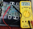
Here are the exact readings when amp is running and distorted signal is coming out of Channel A. DVM Red probe on pins, black probe on chassis.
Pin 1 . -0.35V
Pin 2, -0.03V
Pin 3. -0.02V
Pin 4. 14.61V (+), all other are (-)
Pin 5. -3.17V
Pin 6. -1.19V
Pin 7. -13.45V
Pin 8, -15.21V
This new IC1 does not feel hot , just barely warm after running for 5 minutes or so.
Please let me know what you think about these values.
Thanks,
George
Last edited:
Can you check if the probes are reversed at the meter?Pin 4. 14.61V (+), all other are (-)
Pin 5. -3.17V
Pin 6. -1.19V
Pin 7. -13.45V
Pin 8, -15.21V
Pin8 should be +, pin4 should be - (when black probe to chassis).
For now, I'll assume those readings are just opposite polarity but otherwise correct.
Pin5 voltage indicates there must be DC at the output of Amp B, can you check it?
Georgio_P
Member
- Joined
- Mar 10, 2024
- Messages
- 37
- Reaction score
- 4
Hello G1.1.
Yes, Your were right,
Probes were reversed on my DVM.
I checked Output on Channel B, Tip, and indeed 3.17V showing on meter. Only Channel A in and out plugged in.
Let me know what you think that I should try next.
Thanks,
George
Yes, Your were right,
Probes were reversed on my DVM.
I checked Output on Channel B, Tip, and indeed 3.17V showing on meter. Only Channel A in and out plugged in.
Let me know what you think that I should try next.
Thanks,
George
Last edited:
Georgio_P
Member
- Joined
- Mar 10, 2024
- Messages
- 37
- Reaction score
- 4
Hi G1.1,
Sure thing,
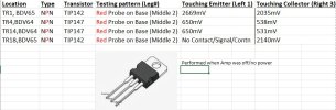
Looking back at my recent order from Mouser, the spec sheet states that the TIP142's (at TR1 and TR18) are NPN , (old BDV65 location), and the TIP147's (at TR4 and TR14) are NPN. (old BDV64 location). I tried testing them as PNP, with black in the middle and red on the ends , and received no readings.
I did set my DVM to Diode mode and take readings at the red probe to the P middle leg, and the black to the N's left and right legs for all 4 Darlingtons while the amp is powered on.
Correction, I tried to get readings when the amp was on, and was getting loud pops when touching base and emitter on TR1, it sounded bad, so I did all this testing with the amp powered off.
Results are in the attachment below.. I am not 100% sure on which legs are E and B and C. but you can tell which legs I tested from the chart below.
Let me know what you think of these results, and if there is a more preferred method to get the Emitter, Base, and Collector readings for these transistors.
Also replaced input jack for Channel A since tip was not making contact with no jack inserted, but no difference noticed.
Thanks,
George
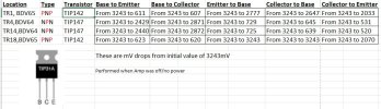
Sure thing,
Looking back at my recent order from Mouser, the spec sheet states that the TIP142's (at TR1 and TR18) are NPN , (old BDV65 location), and the TIP147's (at TR4 and TR14) are NPN. (old BDV64 location). I tried testing them as PNP, with black in the middle and red on the ends , and received no readings.
I did set my DVM to Diode mode and take readings at the red probe to the P middle leg, and the black to the N's left and right legs for all 4 Darlingtons while the amp is powered on.
Correction, I tried to get readings when the amp was on, and was getting loud pops when touching base and emitter on TR1, it sounded bad, so I did all this testing with the amp powered off.
Results are in the attachment below.. I am not 100% sure on which legs are E and B and C. but you can tell which legs I tested from the chart below.
Let me know what you think of these results, and if there is a more preferred method to get the Emitter, Base, and Collector readings for these transistors.
Also replaced input jack for Channel A since tip was not making contact with no jack inserted, but no difference noticed.
Thanks,
George
Attachments
Last edited:
Yes, diode checks or resistance readings need to be done with power off.I tried to get readings when the amp was on, and was getting loud pops when touching base and emitter on TR1, it sounded bad, so I did all this testing with the amp powered off.
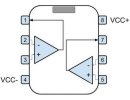
The pinout for all the TIP type transistors in this amp is BCE, from left to right.
What do you mean by 'no contact/signal' ?
Usually a beep or zero reading on diode check function indicates a short.
Georgio_P
Member
- Joined
- Mar 10, 2024
- Messages
- 37
- Reaction score
- 4
Hello G1.1.
On TR18, I held the Red probe on the middle leg, and touched the left leg with black. I got no reading - as if the two probes were not touching anything but air. When I turn it on in Diode mode, it shows / displays 3270 mV or so in the LCD, and that reading never changes on that particular TS18 connection.
Based on these being BCE , 123, Left to right, should I re-take all these readings again but with the red on leg 1, then touching leg 2 to get the Collector and then 3 for the Emitter reading?
Thank you,
George
It sounds like that 3270 is equivalent of 'OL' (over-limit or open) reading on most meters.When I turn it on in Diode mode, it shows / displays 3270 mV or so in the LCD, and that reading never changes on that particular TS18 connection.
For your meter: "if the diode is reverse biased or there is an open circuit the reading displayed will be between 3150mV and 3450mV"
Here is a good write up on the transistor test: https://vetco.net/blog/test-a-transistor-with-a-multimeter/2017-05-04-12-25-37-0700
Because the 142's and 147's are Darlington transistors, the B-E readings will be approximately double that of regular transistors.
Georgio_P
Member
- Joined
- Mar 10, 2024
- Messages
- 37
- Reaction score
- 4
Hello G1.1,
I just did retest the Darlingtons and report back here the readings based on the transistor BCE testing website that you provided.
Please take a look and let me know what you think...
Thank you,
George
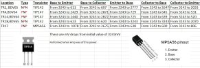
I just did retest the Darlingtons and report back here the readings based on the transistor BCE testing website that you provided.
Please take a look and let me know what you think...
Thank you,
George
Attachments
Last edited:
Sorry, my mistake. With these particular darlington's, there is an added internal resistor which makes them measure the same as normal transistors.Because the 142's and 147's are Darlington transistors, the B-E readings will be approximately double that of regular transistors.
These readings look pretty good but you have the 'type' listings reversed I think. No problem, I will assume the 'location' names are correct.I just did retest the Darlingtons and report back here the readings based on the transistor BCE testing website that you provided.
TR18 'collector to base' reading is different than the others. It makes me think something in a parallel circuit is not right.
Check resistance of R46 and R47.
Do transistor checks on TR17. It's pinout is EBC.
Georgio_P
Member
- Joined
- Mar 10, 2024
- Messages
- 37
- Reaction score
- 4
Hello G1.1
I also noticed that for TR18 on the E-B and on C-B shows no voltage drop. I have an extra TIP142, if we think that should be replaced.
You are correct, I just took the NPN / PNP values from the internet, but I've updated the table on you stating that they were reversed.
R46 reading at 1.18K Ohms, and R47 reading at .214K Ohms, pretty close to the schematic, or so it seems.
I have updated my transistor table below in order to show what I am getting for TR17 today.
Please let me know what you think.
Thanks,
George
Attachments
TR17 readings are about what I would expect.I have updated my transistor table below in order to show what I am getting for TR17 today.
Can you check resistance of R48 and R66. Also check that TR18 solder connections are good.
Georgio_P
Member
- Joined
- Mar 10, 2024
- Messages
- 37
- Reaction score
- 4
Hello G1.1,
R48 is showing 10.1 Ohms, and R66 is showing 0.6 Ohms.
In testing soldering of TR18. I can get continuity from the E leg of TR18 to the E leg of TR4, and from C leg of TR18 to C leg of TR4, but when I try getting a reading from the B leg of TR18 to B leg of TR4, I don't get continuity.
Actually,when I am testing continuity from the B leg of TR18, to anywhere else on the board, I don't have any continuity.
I am thinking that this is a bridge to nowhere, this B leg on TR18..
Let me know what you think, or what else I can try.
Thanks,
George
This is actually good news, as it explains the odd readings for TR18 in circuit.when I try getting a reading from the B leg of TR18 to B leg of TR4, I don't get continuity.
Actually,when I am testing continuity from the B leg of TR18, to anywhere else on the board, I don't have any continuity.
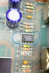
Probably the trace that goes from TR18 base to R48/D8 is cracked. If you remove the solder at TR18 base and look at the trace with a magnifier, you will probably be able to see it.
You can just install a jumper wire from TR18 base to the first place the trace goes (looks like R48). Or use a scrap component lead to bridge across the crack in the trace.
Have a close look at the traces for all the other devices on the heatsink as well. It was evident from the start that some of them had been replaced in the past, before you got the amp I would think.
Georgio_P
Member
- Joined
- Mar 10, 2024
- Messages
- 37
- Reaction score
- 4
Hello G1.1,
That is kind of what I was thinking. I might have cooked off the solder in the trace myself, regardless, I will run a jumper from the base leg on TR18 to R48, then retest the continuity.
Once I get continuity there. I will listen to the output again and let you know ASAP.
Thanks,
George
That is kind of what I was thinking. I might have cooked off the solder in the trace myself, regardless, I will run a jumper from the base leg on TR18 to R48, then retest the continuity.
Once I get continuity there. I will listen to the output again and let you know ASAP.
Thanks,
George
Similar threads
- Replies
- 5
- Views
- 130
- Replies
- 13
- Views
- 816
- Replies
- 4
- Views
- 1K
- Replies
- 0
- Views
- 250