• We are looking to make improvements to the Classifieds! Help us determine what improvements we can make by filling out this classifieds survey. Your feedback is very appreciated and helpful!

    Take survey

A "Retro" JTM 45/100 build

  • Thread starter Sigs
  • Start date
  • This site may earn a commission from merchant affiliate links like Ebay, Amazon, and others.

Sigs

Active Member
Joined
Aug 14, 2020
Messages
292
Reaction score
127
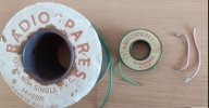
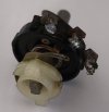
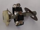
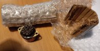
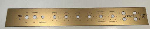
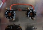
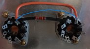
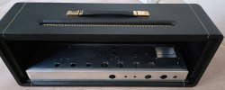
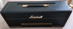
Well, thought it maybe time to make a start, have most of the nos parts required, just need to find large body RS Made in England pots and RS 1K 5 watt wirewound resistors, so if anyone know where to find these please let me know.
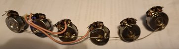
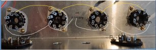
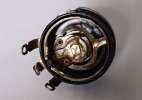
The idea is to build a JTM45/100 as close to a vintage one, so hope all the experts will chime in and offer advice, so for the moment here are a few images.
 

Attachments

  • cab back.JPG
    cab back.JPG
    146.5 KB · Views: 34
  • cab.JPG
    cab.JPG
    161.7 KB · Views: 34
  • chassis.jpg
    chassis.jpg
    217.5 KB · Views: 35
Last edited:

playloud

Well-Known Member
Joined
Dec 28, 2020
Messages
2,442
Reaction score
4,181
Excellent start! Can we see more pics of the RS wire rolls?
 

Sigs

Active Member
Joined
Aug 14, 2020
Messages
292
Reaction score
127
Excellent start! Can we see more pics of the RS wire rolls?
RS wires are 14 strand with 0.0076" dia strands as used in old Marshalls, left to right differences wire are the O.D dias, 0.070", 0.060" and pink wire from a 1959 Marshall year 1970 which is 0.084 dia which came with the pots.
I'd trade these pots for large RS pots.
 

Attachments

  • RS wire.JPG
    RS wire.JPG
    184.6 KB · Views: 11
  • 1959 pots.JPG
    1959 pots.JPG
    77.5 KB · Views: 12

Sigs

Active Member
Joined
Aug 14, 2020
Messages
292
Reaction score
127
So in a "66 JTM45/100, what wire colours did they use ? on pin 6 from V4 to V5 to V6 to V7.
What was used on pin 3 V4 to V5 and PIN 3 V7 to V6 ? was this dependent on the primary wires to the OT ?
 

Attachments

  • 45-100 wire colours.JPG
    45-100 wire colours.JPG
    93.5 KB · Views: 6

TAZIN

Well-Known Member
Joined
Mar 18, 2013
Messages
1,198
Reaction score
1,370
So in a "66 JTM45/100, what wire colours did they use ? on pin 6 from V4 to V5 to V6 to V7.
What was used on pin 3 V4 to V5 and PIN 3 V7 to V6 ? was this dependent on the primary wires to the OT ?
The OT primary link wires (pin #3) tend to be blue for amps in the 6XXX range and red afterwards. Sometimes Marshall ran a red link wire for V4 to V5, and a black wire for V6 to V7.
The link wires for pin #6 vary. Popular choices are: green, blue, red, black, and orange.
 

shakti

Well-Known Member
Joined
Jul 14, 2016
Messages
398
Reaction score
494
Very nice idea, will be following with interest. Most of the large style pots aren’t hard to find if you can settle for used ones that aren’t labeled RS but are otherwise exactly the same. The 5k and 25k are the ones that are somewhat hard to find.
 

Sigs

Active Member
Joined
Aug 14, 2020
Messages
292
Reaction score
127
Very nice idea, will be following with interest. Most of the large style pots aren’t hard to find if you can settle for used ones that aren’t labeled RS but are otherwise exactly the same. The 5k and 25k are the ones that are somewhat hard to find.

I'm looking.....................
Yes, there are AB and some RS pots that have a different internal, this type is almost impossible to modify.
 

Attachments

  • ab-rs.JPG
    ab-rs.JPG
    60.9 KB · Views: 4
Last edited:

shakti

Well-Known Member
Joined
Jul 14, 2016
Messages
398
Reaction score
494
I thought all those Allen Bradley large pots were the same, R/S branded or not? I’ve never taken any of them apart though…
 

Sigs

Active Member
Joined
Aug 14, 2020
Messages
292
Reaction score
127
I thought all those Allen Bradley large pots were the same, R/S branded or not? I’ve never taken any of them apart though…
If you look closely at the shaft where the threaded part is, you'll see a groove with a sort of circlip, this is what secures the assembly on the AB pots, some RS pots are the same as AB, one other pot is the Clarostat with Made in England which is same as a RS made in England which can be stripped down like images shown.
 

Attachments

  • rs1.JPG
    rs1.JPG
    32.4 KB · Views: 4
  • rs2.JPG
    rs2.JPG
    28.6 KB · Views: 4
Last edited:

Sigs

Active Member
Joined
Aug 14, 2020
Messages
292
Reaction score
127
Just found a set of nos McMurdo pre-amp sockets, these will go well the 1966 McMurdo power sockets.
 

Attachments

  • Mcmurdo pre sockets.JPG
    Mcmurdo pre sockets.JPG
    207.3 KB · Views: 6

Matthews Guitars

Well-Known Member
Joined
Aug 17, 2019
Messages
8,853
Reaction score
15,185
If you're going for max authenticity you might want one of my JTM45 plexi panels painted with real bronze powder paint, which Marshall hasn't made since 1969. It'll age just like the originals and turn green if exposed to too much moisture, just like the originals.
 

Attachments

  • JTM45bronzepanel.jpg
    JTM45bronzepanel.jpg
    825.1 KB · Views: 4

Sigs

Active Member
Joined
Aug 14, 2020
Messages
292
Reaction score
127
I see some images where pin 6 to 6 wires are intentionally laid out as shown, what's the reason for this ? is this to minimize some sort of interference from other wires ? do they need to be as per this shape ?
 

Attachments

  • pin 6 to 6.JPG
    pin 6 to 6.JPG
    123.9 KB · Views: 2
Last edited:

playloud

Well-Known Member
Joined
Dec 28, 2020
Messages
2,442
Reaction score
4,181
I see some images where pin 6 to 6 wires are intentionally laid out as shown, what's the reason for this ? is this to minimize some sort of interference from other wires ? do they need to be as per this shape ?

What were you thinking of as an alternative?

It's a pretty good layout as-is. The input grid wires (to pin 5) are more important. In particular, you want to make sure that the wires from the phase inverter (which don't have grid stoppers) cross the orange wires orthogonally, and at the greatest distance possible.

R.G. Keen has a good summary of lead dress: http://www.geofex.com/Article_Folders/lead_dress/lead_dress_in_tube_amps.htm

You'll notice that he lists screen wires as "mildly sensitive" (and you're avoiding interaction with the heater and plate wires pretty nicely with this layout).
 

Sigs

Active Member
Joined
Aug 14, 2020
Messages
292
Reaction score
127
What were you thinking of as an alternative?

It's a pretty good layout as-is. The input grid wires (to pin 5) are more important. In particular, you want to make sure that the wires from the phase inverter (which don't have grid stoppers) cross the orange wires orthogonally, and at the greatest distance possible.

R.G. Keen has a good summary of lead dress: http://www.geofex.com/Article_Folders/lead_dress/lead_dress_in_tube_amps.htm

You'll notice that he lists screen wires as "mildly sensitive" (and you're avoiding interaction with the heater and plate wires pretty nicely with this layout).
I had basically taken the image from your amp images, I thought if the wires were wired as per blue line in my image (this was the alternative), it would interfere with other wires, remember I'm still learning.
 

Attachments

  • pin 6 wires.JPG
    pin 6 wires.JPG
    77.8 KB · Views: 2

playloud

Well-Known Member
Joined
Dec 28, 2020
Messages
2,442
Reaction score
4,181
I had basically taken the image from your amp images, I thought if the wires were wired as per blue line in my image (this was the alternative), it would interfere with other wires, remember I'm still learning.

Ah right. That blue line is suboptimal because of the angle at which it crosses the grid wire. You could definitely make the orange section "tighter" though (i.e. keep it closer to the tube sockets), if you prefer.
 

Sigs

Active Member
Joined
Aug 14, 2020
Messages
292
Reaction score
127
Ah right. That blue line is suboptimal because of the angle at which it crosses the grid wire. You could definitely make the orange section "tighter" though (i.e. keep it closer to the tube sockets), if you prefer.
Much appreciated.
 
Top