• We are looking to make improvements to the Classifieds! Help us determine what improvements we can make by filling out this classifieds survey. Your feedback is very appreciated and helpful!

    Take survey

Building a 5F6-A from the ashes of an old Italian PA amp

  • Thread starter pietro.castelli
  • Start date
  • This site may earn a commission from merchant affiliate links like Ebay, Amazon, and others.

pietro.castelli

Active Member
Joined
Aug 18, 2021
Messages
95
Reaction score
190
I then proceeded to test the effect of my little contraption.
First of all, the pilot light turned on when I flicked the switch:

960x0.webp


Then I measured the heaters voltage at the power supply:

unnamed-3.jpg


unnamed.jpg


and at the pilot light:
unnamed-2.jpg


unnamed-5.jpg


You might argue that 6.67 volts was still okay, but the mains voltage was particularly low when I took the measurement.
In my previous tests, I've seen the power supply produce more than 7 volts at the heaters.
 
Last edited:

2L man

Well-Known Member
Joined
Sep 30, 2020
Messages
412
Reaction score
295
I then proceeded to test the effect of my little contraption.
First of all, the pilot light turned on when I flicked the switch:

960x0.webp


Then I measured the heaters voltage at the power supply:

unnamed-3.jpg


unnamed.jpg


and at the pilot light:
unnamed-2.jpg


unnamed-5.jpg


You might argue that 6.67 volts was still okay, but the mains voltage was particularly low when I took the measurement.
In my previous tests, I've seen the power supply produce more than 7 volts at the heaters.
Something very strange if filament AC voltage is more than 7V one day and 6V on another!!!

Connect somekind load to it.

Transformer output voltages should come proportional to input voltage and 6V vs 7V is about 17% difference which should never happen for Mains voltage.
 

pietro.castelli

Active Member
Joined
Aug 18, 2021
Messages
95
Reaction score
190
Something very strange if filament AC voltage is more than 7V one day and 6V on another!!!

Connect somekind load to it.

Transformer output voltages should come proportional to input voltage and 6V vs 7V is about 17% difference which should never happen for Mains voltage.

Hi,
6V is the reading after the dropping diodes.
The highest voltage I’ve read on the heaters at the power supply is 7.06V. The lowest was 6.67V. That’s about a 5% difference which is the coherent with the fluctuation I get sometimes here on the mains voltage
 

pietro.castelli

Active Member
Joined
Aug 18, 2021
Messages
95
Reaction score
190
Today I finished the heaters circuit, wiring all the tubes sockets:

IMG-1612.jpg


Meanwhile I’ve also started working on the stand by switch, where the B+ from the rectifier is going to be wired.
I’ve added a capacitor and resistor in parallel which should remove any pop:

IMG-1609.jpg


The capacitor is 0.047 uF 630v and the resistor is 100k 2W
 

pietro.castelli

Active Member
Joined
Aug 18, 2021
Messages
95
Reaction score
190
Yesterday, I wired the two bridge rectifiers for the B+ and Bias supply.
I must admit it kicked my butt a bit more than expected. It's a lot of wiring to tuck in a relatively small area. Also, working with eyelets is far less enjoyable compared to turrets. When you have a single eyelet hosting multiple components leads plus wiring, it is a tight squeeze.

unnamed-1.jpg


This is the wiring bundle so far near the power section (still waiting for lacing tape), with the grounding strip I've mounted to the chassis.

unnamed.jpg


I've also started to assemble the filter capacitors board:

unnamed-2.jpg


And finally, an overview of the chassis so far:

unnamed-3.jpg
 
Last edited:

Marcomel79

Well-Known Member
Joined
May 3, 2021
Messages
1,822
Reaction score
2,675
Location
Oslo
Looking very nice Pietro. Someting my father always told me: people never ask how long it took, but they always ask who made it:)
 

pietro.castelli

Active Member
Joined
Aug 18, 2021
Messages
95
Reaction score
190
Looking very nice Pietro. Someting my father always told me: people never ask how long it took, but they always ask who made it:)

That's a very good lesson to learn!
And I also inherited my passion for tinkering with things and building stuff from my father!
 

pietro.castelli

Active Member
Joined
Aug 18, 2021
Messages
95
Reaction score
190
Today I did some more work on the tube sockets,
adding the screen resistors, wiring the OT primary, and so on:

IMG-1662.jpg


Wiring is still a bit of a rat’s nest. Still waiting for the lacing tape to get things tidied up. I’ve also added some taps to measure the bias of each tube.
I know it’s not the most accurate way of measuring, but it helps getting in the ballpark:

IMG-1666.jpg


Finally I’ve populated the main circuit board with most of the components:

IMG-1668.jpg


I must say I’m pretty happy with the way the
build is coming along so far.
 

StingRay85

Well-Known Member
Joined
Aug 18, 2019
Messages
3,464
Reaction score
3,722
Amazing work so far.

Be aware that heater voltage under load might still drop, and your board to drop voltage might become redundant
 

pietro.castelli

Active Member
Joined
Aug 18, 2021
Messages
95
Reaction score
190
Amazing work so far.

Be aware that heater voltage under load might still drop, and your board to drop voltage might become redundant

Thanks!
Yes, I’m aware but it isn’t a big deal.
Worst case scenario I’ll remove the diodes and
keep the virtual center tap only.
 

pietro.castelli

Active Member
Joined
Aug 18, 2021
Messages
95
Reaction score
190
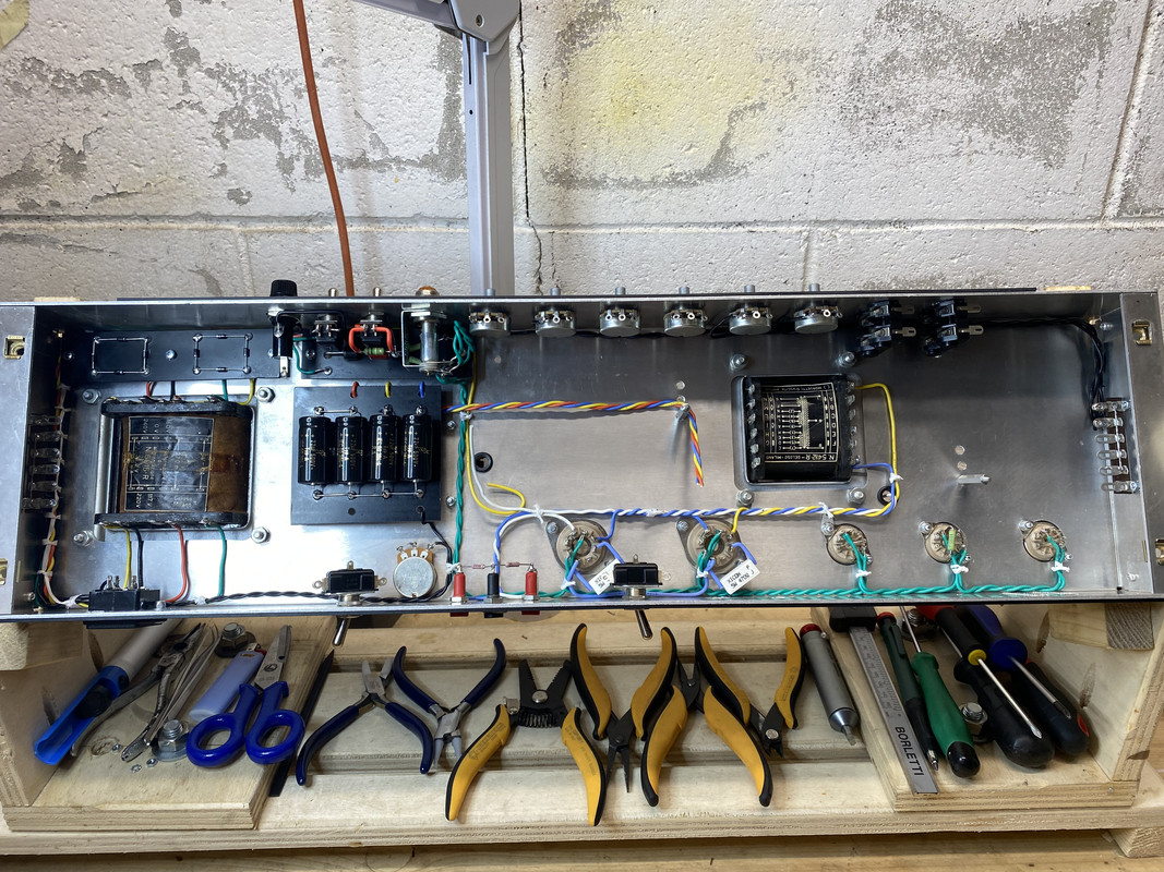
After two much needed weeks of holidays, the amp build continues:

First I changed the routing of the output transformer primary to tubes’ plates connections as well as some mistakes I’ve made wiring the tube sockets. Thanks @Marcomel79 for spotting them!

IMG-2686.jpg


Since I’ve finally received the lacing tape I’ve ordered, I also started tiding up the wiring:

IMG-2684.jpg


IMG-2682.jpg


Meanwhile I’ve also wired the filter capacitors board, and made some progress with the tedious job of attaching all the hook-up wires to the main circuit board.
 

2L man

Well-Known Member
Joined
Sep 30, 2020
Messages
412
Reaction score
295
Your building skill is very good and look neat! :)

Chassis electrical role is Safety Earth! If both ends soldering strips "buses" have connect to Chassis there will flow some HV current thru Chassis and it open possibility for hum and noise enter to audio.

Safety Earth wire can have EM noise because it always has resistance and impedance and often run long length with Live and Neutral. Electric regulations has already about 50 years forbid to flow current in SE.

HV0VDC / Signal Reference should have only one connection point with Chassis and then no secondary current leak to Chassis because it does not have other return point. If does not matter is the connection close to power supply or close to input jacks but signal input is more common place.
 

Marcomel79

Well-Known Member
Joined
May 3, 2021
Messages
1,822
Reaction score
2,675
Location
Oslo
Your building skill is very goon and look neat! :)

Chassis electrical role is Safety Earth! If both ends soldering strips "buses" have connect to Chassis there will flow some HV current thru Chassis and it open possibility for hum and noise enter to audio.

Safety Earth wire can have EM noise because it always has resistance and impedance and often run long length with Live and Neutral. Electric regulations has already about 50 years forbid to flow current in SE.

HV0VDC / Signal Reference should have only one connection point with Chassis and then no secondary current leak to Chassis because it does not have other return point. If does not matter is the connection close to power supply or close to input jacks but signal input is more common place.
If you look carefully the first tag is not connected to the other ones...
 

pietro.castelli

Active Member
Joined
Aug 18, 2021
Messages
95
Reaction score
190
Looking like a work of art!

This looks like Hiwatt wiring quality, amazing

Thanks a lot guys!
I'm rather OCD, so I'm trying to do a neat build, but I'm still a rookie (this is my second amp), so I make a lot of mistakes :D


If you look carefully the first tag is not connected to the other ones...


If I got @2L man's comment correctly, he suggests separating Safety Earth from grounding.
I indeed disconnected the last tag of the stripboard to avoid ground loops, but the first tag carries the earth connection, and the following one carries ground connections. I should have probably separated the first tag instead.

Just to simplify things, here's a rough sketch of how things are connected at the moment:

IMG-2684.jpg
 

Marcomel79

Well-Known Member
Joined
May 3, 2021
Messages
1,822
Reaction score
2,675
Location
Oslo
Thanks a lot guys!
I'm rather OCD, so I'm trying to do a neat build, but I'm still a rookie (this is my second amp), so I make a lot of mistakes :D


If I got @2L man's comment correctly, he suggests separating Safety Earth from grounding.
I indeed disconnected the last tag of the stripboard to avoid ground loops, but the first tag carries the earth connection, and the following one carries ground connections. I should have probably separated the first tag instead.

Just to simplify things, here's a rough sketch of how things are connected at the moment:

IMG-2684.jpg
Thats exactly what i thought you were gonna do. It does make more sense to connect the earth ground separate and sll the other grounds together!
 

pietro.castelli

Active Member
Joined
Aug 18, 2021
Messages
95
Reaction score
190
Thats exactly what i thought you were gonna do. It does make more sense to connect the earth ground separate and sll the other grounds together!

Of course, it makes a lot more sense. I don't know why I've connected Earth that way, but at least is is going to be an easy fix. As I've mentioned, I still have a lot to learn :dude:
Thanks to you and @2L man for pointing me in the right direction!

Cheers!
 

Latest posts


Top