• We are looking to make improvements to the Classifieds! Help us determine what improvements we can make by filling out this classifieds survey. Your feedback is very appreciated and helpful!

    Take survey

Channel Foot Switch interface on my DLS1H kills output

  • Thread starter Gordon Rankin
  • Start date
  • This site may earn a commission from merchant affiliate links like Ebay, Amazon, and others.

Gordon Rankin

New Member
Joined
Aug 10, 2021
Messages
10
Reaction score
8
All,
So I have been fighting what I thought was a tube or amp problem for a couple of days. I have the 50th anniversary issue DSL1 with dual channels. I pulled the tubes and replaced one at a time no go no output. So I pulled the amp out put it on my bench and it worked fine??? So then I put it back in the rig I was using to test it and sure enough works fine. Plug in the Marshall channel switcher and fire up the amp and everything works fine. Hit the footswitch and nothing, hit a again and nothing. OK turn it off pull the foot switch out of the amp and check the continuity and it's fine so it must be something with the interface of the front panel switch (which works as long as the foot switch is out of circuit) and the external foot switch input.

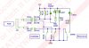
There are no schematics for this version which has dual ECC82/12AU7A outputs. Only can find the single channel version.
Contacted support and everyone knows how that goes...
Any thoughts?
Thanks,
Gordon
 

PelliX

Well-Known Member
Joined
Jun 16, 2020
Messages
7,312
Reaction score
14,800
Welcome to the forum :welcome:

So, let me just re-cap this for clarity; when no footswitch is connected, the amp works as expected. When the footswitch is connected, the amp works fine until the channel switch is performed by means of this footswitch, at which point there is no output anymore. Repeatedly operating the footswitch does nothing, but turning the amp off and back on again remedies the situation again. Is that correct?

If I understood the problem correctly, here are a few speculations. It could be the microcontroller (ATtiny, I believe) locking up, which would explain why further actions have no effect until a power cycle occurs. Off the top of my head I'm not quite sure whether the footswitch uses the same digital input on the controller as the button on the front, but I can check that.

Have you checked the obvious things like the input jack itself or any loose connections in the footswitch?
 

Gordon Rankin

New Member
Joined
Aug 10, 2021
Messages
10
Reaction score
8
Welcome to the forum :welcome:

So, let me just re-cap this for clarity; when no footswitch is connected, the amp works as expected. When the footswitch is connected, the amp works fine until the channel switch is performed by means of this footswitch, at which point there is no output anymore. Repeatedly operating the footswitch does nothing, but turning the amp off and back on again remedies the situation again. Is that correct?

If I understood the problem correctly, here are a few speculations. It could be the microcontroller (ATtiny, I believe) locking up, which would explain why further actions have no effect until a power cycle occurs. Off the top of my head I'm not quite sure whether the footswitch uses the same digital input on the controller as the button on the front, but I can check that.

Have you checked the obvious things like the input jack itself or any loose connections in the footswitch?

Thanks, and you are correct with your assumption.
No loose connections and I guess I can look at the microcontroller. I do some programming and while I use Microchip PIC controllers I do have an FAE that might be able to help me out if that is the problem.
But really the micro is just going to take input FP and input SWITCH and then activate the appropriate relay, correct? I don't think it's the micro though because I can still hear the obvious hum and in the clean setting it sounds one way and in the crunch setting it sounds different. But the level is down (other than hum) is down like 50dB.
Thanks,
Gordon
 

PelliX

Well-Known Member
Joined
Jun 16, 2020
Messages
7,312
Reaction score
14,800
I do some programming and while I use Microchip PIC controllers I do have an FAE that might be able to help me out if that is the problem.

Ah, nice! If you know your way around microcontrollers, dumping an Atmel is easy (if you need to flash the replacement). :)

But really the micro is just going to take input FP and input SWITCH and then activate the appropriate relay, correct?

I don't think so. I don't have the exact schematic of this model, neither do I have one to test with, but I believe a muting relay is engaged at channel switch to prevent a thump/click. On other DSLs this is marked as RL_MUTE on the schematic.

I don't think it's the micro though because I can still hear the obvious hum and in the clean setting it sounds one way and in the crunch setting it sounds different. But the level is down (other than hum) is down like 50dB.

Well, the hum from the output stage would be there even if RL_MUTE is in fact engaged, it splits the pre-amp from the power section, simply put. But you're saying that there is still sound, just...faint?

Also, as you undoubtedly know, microcontrollers can be touchy without a stable power supply, did you have a chance to look at the DC for the chip?
 

Gordon Rankin

New Member
Joined
Aug 10, 2021
Messages
10
Reaction score
8
Ok you may have a point about the mute as it's now stuck in mute without the foot switch or trying to change the channel via the FP.

I will pull the amp out and check and see what the problem is. Those micro's work at any voltage from 2.5->5.5V and they are pretty tolerant. I would imagine the micro is feeding a transistor to pull the 25ma required for those types to go active. I bet one of the damn bleed diodes is bad and the damn mute thingy is getting stuck on. I bet if I leave it off for a long period of time it will work again and then die after a couple of channel switches.

Thanks,
Gordon
 

PelliX

Well-Known Member
Joined
Jun 16, 2020
Messages
7,312
Reaction score
14,800
I will pull the amp out and check and see what the problem is. Those micro's work at any voltage from 2.5->5.5V and they are pretty tolerant. I would imagine the micro is feeding a transistor to pull the 25ma required for those types to go active. I bet one of the damn bleed diodes is bad and the damn mute thingy is getting stuck on. I bet if I leave it off for a long period of time it will work again and then die after a couple of channel switches.

Yup, but they can get quirky on fluctuating voltages. You're (most likely) correct about the transistor, that is the standard setup in a DSL. Let me know your findings when you've taken a close(r) look. :)
 

Gordon Rankin

New Member
Joined
Aug 10, 2021
Messages
10
Reaction score
8
Ok no micro, only switching relay. I can't see any diode bleed on this thing. Will check if the damn relay is just dead. I do always have this problem if the external switch is plugged in which disables the front switch so maybe adding a diode will fix this. I have used a bunch of relays that look like this. None of them have diodes inside. Maybe Marshall engineers were thinking the 2 leds may do that :) Opps...
 

Attachments

  • IMG_5563.jpg
    IMG_5563.jpg
    743.5 KB · Views: 4

Gordon Rankin

New Member
Joined
Aug 10, 2021
Messages
10
Reaction score
8
Ok so it appears there are 2 relays both DPDT, and here is the switching that seems to be the same as this one from a different schematic.
Ok so Relay 2, in the clean mode bypasses the overdrive and mutes the overdrive circuit. Relay 1 in clean mode enacts a -12dB gain. So basically in overdrive the signal is 12dB up and goes through another 12AX7A gain stage with standard marshallish filtering.
Of course the 2 relays are different. Since in both cases the signal is muted.... I got to probe around with a signal to figure out which one without a schematic. Lucky me!
Thanks,
Gordon
 

Attachments

  • relay.jpg
    relay.jpg
    121.3 KB · Views: 4

Gordon Rankin

New Member
Joined
Aug 10, 2021
Messages
10
Reaction score
8
Day 3
Ok this happens before the FX loop. Unlike the schematic I have for some other 1W unit, this one uses an MPSA42 as the emitter follower to send to the FX loop instead of 1/2 of the 12AU7/ECC82.
The weird thing is neither of the relays that should feed this thing are anywhere near the transistor. Ok the two relays RL1 and RL2:
RL1 is near the clean channel Gain and Volume. Unlike the schematic I have both of the SPDT are being used and while I can't find the pole input to either side, I can see my signal coming out both sides. Ok.... simple mistake on my hand. The relay nominclature on my schematic are opposite of what i have. RL1 on mine is a DPDT and RL2 is a SPDT. So maybe I need to look at RL2 as that might be the whole problem.

Called two service places in town and they said thanks. Great....
Gordon
 

Gordon Rankin

New Member
Joined
Aug 10, 2021
Messages
10
Reaction score
8
All,
Day 4 a friend sent me the schematics and it looks like I have a couple of iffy solder joints. Why do I say that? Well the OD channel is working all the time now. But the clean channel seems to die at the VOL control..... and now when I plug it in the back... now everything is working. Oh well, if it has a problem now at least I have the schematics.
Thanks,
Gordon
 

Latest posts


Top