• We are looking to make improvements to the Classifieds! Help us determine what improvements we can make by filling out this classifieds survey. Your feedback is very appreciated and helpful!

    Take survey

Completed JohnH Attenuators?

  • Thread starter Gene Ballzz
  • Start date
  • This site may earn a commission from merchant affiliate links like Ebay, Amazon, and others.

Gene Ballzz

Well-Known Member
Joined
Feb 19, 2013
Messages
4,697
Reaction score
6,521
Location
Las Vegas, NV
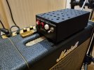
Now, these I would not be embarrassed to have sitting on top of my amp, onstage! Although, these two were built for a couple friends!

My sincerest thanks to @DeluxeReverb for the inspiration to switch over to countersunk metric screws, for resistor mounting and to @Dblgun for the "gutter grate" idea! I think both ideas brought the cosmetic and functional level up a couple notches! :cheers:

And of course, a special thanks to @JohnH for all the brilliant work and support!

Contact me privately with any questions.

Still Attenuatin'
Gene

IMG_0681.jpegIMG_0682.jpegIMG_0683.jpegIMG_0680.jpeg
 
Last edited:

JohnH

Well-Known Member
Joined
May 31, 2008
Messages
6,156
Reaction score
5,062
Location
Wilton NSW
Hi Gene, these new units look really good - great work!. Im proud of them too!

Getting to a place where we have such a well executed and proven design continues to be a great ride. I really enjoy the collaboration and none of us would be here on our own!

Onward!
 

Gene Ballzz

Well-Known Member
Joined
Feb 19, 2013
Messages
4,697
Reaction score
6,521
Location
Las Vegas, NV
Hi Gene, these new units look really good - great work!. Im proud of them too!

Getting to a place where we have such a well executed and proven design continues to be a great ride. I really enjoy the collaboration and none of us would be here on our own!

Onward!

@JohnH

You are certainly correct my friend, about the collaboration factor! I've developed and nearly worked out the bugs for drilling templates, for this size or any larger box! You simply print them out on peel & stick project paper, put them on the box, punch the marks and drill it! Saves a lot of time and effort on layout! Yeah, it still requires a variety of drill bits and some holes are clearly marked as countersunk (for component mounting), but I've allowed for those mounting holes to be just enough oversize to accommodate the slightly different mounting hole centers of various resistor suppliers! Worst case is that the Vishay/Dale resistors made in Mexico end up ever so slightly skewed from the others! I'm gonna go crank my guitar/amp setup, in both 8Ω and 16Ω modes on both 8Ω and 16Ω units for sonic comparison. I'll keep you posted on the results!

Thank Again,
Gene
 

C-Grin

Well-Known Member
Joined
Nov 8, 2020
Messages
1,170
Reaction score
3,344
Location
edge of the Mt. Hood national forest
There it it sits, I am really impressed. Great design and execution. I was concerned that the compensation for the high end loss would sound off, but not at all. It is a thing of beauty and works beyond my expectations. I am very grateful for the thread the designers and the builder (you know who you are). I was skeptical when I first saw the thread as most of the devices I have tried over the years left me disappointed, but no more.

:cheers:

IMG_1157.jpg
 

pietro.castelli

Active Member
Joined
Aug 18, 2021
Messages
95
Reaction score
190
Hi Folks,
I’m very interested in the simple attenuator.
I would really like to build one to tame the plexi 51 all access I’m finishing, but I’m afraid the 50w version will be struggling to deal with the amp.

Has anybody succesfully built a 100w version of the attenuator? What changes are required over the standard?

I apologize if this has already been discussed in the original thread, but the latter gee almost 150 pages long

Thanks to anybody willing to help!
 
Last edited:

JohnH

Well-Known Member
Joined
May 31, 2008
Messages
6,156
Reaction score
5,062
Location
Wilton NSW
Hi @pietro.castelli

For 100W amps, we double all resistor power ratings, get a coil based on 16 gage wire and add a fan. The simplest way to do that is a 12 Volt DC fan, and run it to a 9V wall wart. Use a thick aluminum diecast case and plenty of holes for venting. Please post in main thread if any questions.
 

emann

New Member
Joined
Aug 24, 2022
Messages
27
Reaction score
13
Just finished an M2 with a bypass switch on the back. I know that vent holes in the top are ideal, but I’ve got lots of holes on the sides and bottom, and I’m using it with 20w or less amps (Deluxe Reverb, SV20, etc.). Even after 2 hours of running the amps at 60% and at heavy attenuation, the top of the case where the components are mounted only got to body temperature. Seriously, my cat is warmer.

My bases of comparison are a Weber MiniMass and the attenuator built into my 12w Aiken Tomcat, and this M2 is the best of the lot! Lettering to come later.

Oh, and Hello all from my first post! I joined this forum based on the attenuator design thread. Thanks, @JohnH and the others who contributed to this project.

Update: My total cost for this build was right around $185USD. I went with Mouser for the enclosure and resistors, Parts Express for the inductor, and Antique Electronic Supply for the remainder of the components. I could have saved money by ordering from eBay or other sources, but I’ve had a lot of experience with the suppliers I used for this build, and I knew I’d get the parts quickly.

Oh, and I did end up wiring a connection from the enclosure to the shield of the amplifier input jack after these pics were taken. Before that, touching any non-painted part of the enclosure like the switches or exposed screws would make a super-loud oscillation noise through the speakers. Having a chassis connected in this way is pretty common for attenuators, so it’s the first thing I tried and it completely resolved the issues I was having. Using an ordinary Switchcraft-style jack at the amp input would’ve solved the noise also.

View attachment 106726View attachment 106727

View attachment 106724View attachment 106725
Hello,

I am interested in this build and note that you also mention the Deluxe Reverb. I have a Fender 65 DRRI myself too and wanted to ask you how does the attenuator work with this amplifier.

I am currently checking out some prices for suppliers in Europe and want to build the unit based on the circuit with the lineout so that I can connect to my audio interface and record in the DAW.

Can I ask you what type and size of case did you use please? Also, what is shown in the circuit as the L1 pad - is that the coil of wire you have in the middle of the case attached with tiebacks?

Finally, what is the purpose of the black knob, this does not show in the circuit that I am following.

Thanks for your assistance.
 

rowandg

New Member
Joined
Nov 25, 2022
Messages
8
Reaction score
12
I am looking for an attenuator for my SV20C. Is the JohnH build DIY?

On a side note: at loud volumes something inside the cab resonates when I play a low B or C. Anyone else having this issue?
 

Gene Ballzz

Well-Known Member
Joined
Feb 19, 2013
Messages
4,697
Reaction score
6,521
Location
Las Vegas, NV
I am looking for an attenuator for my SV20C. Is the JohnH build DIY?

On a side note: at loud volumes something inside the cab resonates when I play a low B or C. Anyone else having this issue?

@rowandg ,
FIRST> :welcome: to the forum!
NEXT> This thread is intended for showing off completed units, but the main discussion thread is linked below:


With that said yes, the JohnH is a DIY, but there are a couple/few folks who can do the build for you. Knowing what part of the world you are located in will help us help you with sourcing materials for a build and/or let us know if a completed one can realistically be built and shipped to you! Few of these get built with that "horrid" lead free, RoHS compliant solder, so international shipping can be a little dicey!

Aagain, :welcome:,
Gene
 

rowandg

New Member
Joined
Nov 25, 2022
Messages
8
Reaction score
12
@rowandg ,
FIRST> :welcome: to the forum!

With that said yes, the JohnH is a DIY, but there are a couple/few folks who can do the build for you. Knowing what part of the world you are located in will help us help you with sourcing materials for a build and/or let us know if a completed one can realistically be built and shipped to you! Few of these get built with that "horrid" lead free, RoHS compliant solder, so international shipping can be a little dicey!

Aagain, :welcome:,
Gene
Thank you! I'd love for us to continue the conversation, could you start it? I think because I am new I cannot message you personally.
 

Dblgun

Well-Known Member
Joined
Jan 6, 2019
Messages
786
Reaction score
1,475
Location
AZ
Beautiful builds man! Do you have a schematic for the one in the last pic?

Marco
Hey Marco, I wish I could take credit but it's a pretty straight up John H and Gene Ballz layout. I simply put it into the package I wanted. If you want any info on what I did let me know.
 

rowandg

New Member
Joined
Nov 25, 2022
Messages
8
Reaction score
12
Hey guys, I am happy to say I'm a proud owner of the JohnH attenuator. Amazing build by Gene, and he was kind enough to take the trouble and ship it out to me (US > NL).

I recorded a DI signal and reamped it for every setting, to compare how much the signal changes. At the end (01:05), I sequenced short passages so you can really hear there is no audible difference between Bypass and full attenuation, which is amazing.

Amp settings: normal 8, high 10 all clips normalized.
Attenuator settings:
- Bypassed
- Active (7dB attenuation)
- 10.5dB
- 14dB
- 21dB
- 31.5dB


Attachments

  • 20221219_120617.jpg
    20221219_120617.jpg
    899.7 KB · Views: 41
Last edited:

JohnH

Well-Known Member
Joined
May 31, 2008
Messages
6,156
Reaction score
5,062
Location
Wilton NSW
Hi @rowandg , thankyou very much for those sound clips, and nice build Gene!

Consistent clips like that that step down through the settngs from full volume and then normalize them are a great proof of the design intent. I hope its ok - but Ive linked your post as a reference into the 1st post of the design and testing thread.
 

rowandg

New Member
Joined
Nov 25, 2022
Messages
8
Reaction score
12
Hi @rowandg , thankyou very much for those sound clips, and nice build Gene!

Consistent clips like that that step down through the settngs from full volume and then normalize them are a great proof of the design intent. I hope its ok - but Ive linked your post as a reference into the 1st post of the design and testing thread.
Hey John, a consistent sound across all attenuation levels was very important to me. The results were beyond expectation and I'm glad I could be of help :) Gene's build indeed is great, very professionally built. And thanks to you for creating this device! Such a great studio asset.
 

K Dub

Active Member
Joined
Jun 23, 2022
Messages
45
Reaction score
120
@rowandg In addition to those great sound clips, I would like to add that your JohnH Attenuator looks very nice sitting on top of that SV20C!
 

AtomicRob

Well-Known Member
Joined
Feb 4, 2009
Messages
655
Reaction score
776
Location
California
After much delay... my 100W 16ohm M2 build is done. This was built in a salvaged case from an old car audio amp, which has a massive heat sink on top and sides. The front panel is 1/4" black acrylic, laser cut and engraved on a Glowforge laser cutter. I "experimented" with filling in the etched lines on the front with paint, which sort of didn't work well but I decided I like it looking a bit distressed anyway. I couldn't do the back panel in acrylic because I didn't have jacks that work in a 1/4" thick panel, and thin acrylic is too flexible.

Schematic follows the M2 50W version with all the ratings doubled - except a couple resistors R6 and R7 which according to my ltspice sim only dissipate about 4W and 8W each even with a 170W input like a superlead. So those are just the usual 25W parts. R1 is two 100W parts in parallel. I used Carling mini-toggles for the stages as these never see more than about 2.5A current, so the 5A mini toggle is ok. Bypass and cab switch are full size 10A rated toggles. Inductor is a 15ga part from partsexpress. Internal wiring is all 18ga. The cab switch is mostly for convenience at home, where I usually have two different cabs in the music room - so I can keep them both hooked up. I originally was going to have a dual input switch but decided to use it for bypass instead. In hindsight it's so transparent I should have just not bothered with the bypass and done the input switch, oh well next time.

I don't have any gut shots but let's just say it's not my proudest soldering job. I felt like a real beginner getting good joints on those 100w Arcol resistors, and that's with a fairly high-end soldering station. Ended up using an absurdly large chisel tip and plenty of extra liquid flux.

Sound quality is amazing, many thanks to @JohnH for this great design!

DSCF7042.jpg
IMG_20221226_205232~2.jpg
 
Top