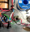
Completely Out of My Depth - Modulus 50w 69 Build

  • Thread starter kingfredward
  • Start date
  • This site may earn a commission from merchant affiliate links like Ebay, Amazon, and others.

BlueX

Well-Known Member
Joined
May 5, 2020
Messages
2,673
Reaction score
5,630
Location
Sweden
It’s wired in now . Couldn’t fit it In the hole but rested it between them will this be okay?

View attachment 157979

Also wired in the indicator light it’s not pretty but should be fine?

Also twisted the green wires to make it look neater
View attachment 157982
View attachment 157980View attachment 157981
Some comments:
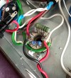
- 10k/3W resistor will probably work, but I usually make a narrow "U" on one lead that will go around the lead from the 470R (for mechanical support).

- You have surrounded the V5 socket with heater wires. It is better to rout them on one side, to minimize hum. Don't know how sensitive the power amp sockets are, though.

- Is p1 on V4/5 connected to ground? Can't see any solder there.

- Lamp wires (AC) are routed in same bundle as OT primaries (to V4/5p3). I would separate them, and try to cross at 90° instead.

- Also, looks like you need to clean the sockets, to avoid shorting between lugs. Important!
 

kingfredward

Well-Known Member
Joined
Sep 30, 2022
Messages
92
Reaction score
288
IMG_8080.jpegIMG_8078.jpeg
Heater wires reworked to one side
IMG_8075.jpeg

Inputs complete too

Getting there I suppose
 

Attachments

  • IMG_8072.jpeg
    IMG_8072.jpeg
    424.3 KB · Views: 2
  • IMG_8073.jpeg
    IMG_8073.jpeg
    399.2 KB · Views: 3
Last edited:

PelliX

Well-Known Member
Joined
Jun 16, 2020
Messages
7,243
Reaction score
14,712
Yup, certainly! You might still get a bit of hum, but try it and see - it might just be as quiet as a graveyard. Before you do, be sure to brush and shake out those solderballs, though. Those can ruin your day. Also there are some stuck to the leads. You should be able to pick them right off without any significant force/effort.

IMG_8078.jpeg

That left power valve socket needs some cleaning up, though. I see you've also chipped a bit out of the resistor. It'll be fine, likely, though. Bending the tabs outwards on the socket can help in A) reducing the chance of flashover (spark gap) and B) make it easier to solder things in place sometimes. Just sayin'.
:)
 

BlueX

Well-Known Member
Joined
May 5, 2020
Messages
2,673
Reaction score
5,630
Location
Sweden
I would still re-route the OT primaries (red, white, and maybe also brown) in the way that Marshall did it. Pic's below from a Marshall JMP50 from '69 (1986 Bass model, instead of 1987 Lead model which I guess you're building). Red and white wires run straight across chassis, between V4 and V5, and connects to each p3. Brown wire is connected on board, but you could follow red/white 'til just before V5, and go to the filter cap.

One reason is that you might need to swap places for red and white. Sometimes the amp will squeal, and then you need to do this swap (difficult to know if in advance).

Also, I don't like that these high voltage (probably 420 VDC) wires run by the sharp edges on the PT mounting plate.

Resto08d.JPGResto09d.JPG
 

kingfredward

Well-Known Member
Joined
Sep 30, 2022
Messages
92
Reaction score
288
Thanks all for your suggestions. I am at an impass now considering I have still not received the diagram of the updated layout without the impedance selector

I have bent the tabs outwards and I have updated of the transformer wires

IMG_8092.jpeg
 

BlueX

Well-Known Member
Joined
May 5, 2020
Messages
2,673
Reaction score
5,630
Location
Sweden
OT primaries look better know! Good that you saved some extra length on the white if you need to swap.

Still a comment on the black choke wires (these are also high voltage). You're using rubber grommets for protection when routing wires through chassis, but route one black choke wire through hole in PT mounting plate without. I would twist them as long as they run together, and run them shortest way to the cap (with some slack). I might be overly cautious, but it would be a better electrical installation.

If you don't get wiring instructions for speaker connections we can probably help you. Need to confirm the following:
- Three speaker outs (one of each of 4, 8, 16 Ohm)
- Just Presence pot, or both Resonance and Presence pots? (seems like "Deep Fried..." has R and P)
 

kingfredward

Well-Known Member
Joined
Sep 30, 2022
Messages
92
Reaction score
288
Thanks for your response. Ill rework the wires later when I have the chance.

RE Need to confirm the following:
- Three speaker outs (one of each of 4, 8, 16 Ohm) -> I have all three
- Just Presence pot, or both Resonance and Presence pots? (seems like "Deep Fried..." has R and P) -> I only have the presence pot

Looking forward to hear what you think
 

BlueX

Well-Known Member
Joined
May 5, 2020
Messages
2,673
Reaction score
5,630
Location
Sweden
Thanks for your response. Ill rework the wires later when I have the chance.

RE Need to confirm the following:
- Three speaker outs (one of each of 4, 8, 16 Ohm) -> I have all three
- Just Presence pot, or both Resonance and Presence pots? (seems like "Deep Fried..." has R and P) -> I only have the presence pot

Looking forward to hear what you think
In case you don't know about switching jacks: There are two lugs each for tip, (ring), and sleeve. One of them is switching, and disconnects when plugging in. This is used in the inputs you wired, to get different functionality when plugging into High or Low input.

Same kind of jacks are often used for speaker out, but here you don't use the switching function. Instead, the non-switching lug is used. If you don't know which is which it's better bridging both lugs (for tip and sleeve, respectively). This is important, since a disconnecting lug takes away the speaker load and you risk destroying expensive parts in the amp!

Your OT probably has four secondary wires, colour coded for 4, 8, and 16 Ohm, and Common.

According to the pic below, connect all six sleeve lugs together and connect Common here. This should also be grounded, typically to chassis at V4 (together with p1 and p8) unless you have a different grounding scheme

Connect 4, 8, and 16 Ohm wires to tip on each jack as marked by green, red, and yellow wires in pic.

Purple wire indicates NFB wire, which connects to board at the purple arrow in next pic. Another wire connects after NFB resistor at next purple arrow to empty lug on presence pot in third pic.

Using 8 Ohm for NFB is common, but 4 or 16 Ohm can also be used (as well as different resistor value like 27k, 47k, or 100k).

Speaker jacks.JPGNFB1.jpegNFB2.jpeg
 
Last edited:

kingfredward

Well-Known Member
Joined
Sep 30, 2022
Messages
92
Reaction score
288
Thanks for the clarification on all this. Please note I have grey (16), green (8), yellow (4) and orange no clue what that is .

How would you wire it in this instance? thanks

1727372120280.png

This is it on the deep fried amp

1727372150862.png

Seems to be connecting on two points on the turret board in this instance
 

BlueX

Well-Known Member
Joined
May 5, 2020
Messages
2,673
Reaction score
5,630
Location
Sweden
Thanks for the clarification on all this. Please note I have grey (16), green (8), yellow (4) and orange no clue what that is .

How would you wire it in this instance? thanks

View attachment 158157

This is it on the deep fried amp

View attachment 158158

Seems to be connecting on two points on the turret board in this instance
What's the parts number for your OT? Modulus has technical info for their trafos on the web page. You need to get this right!

The "Deep Fried..." has speakers grounded at the board (black wire) instead of at V4. The board layout is also very different to yours. It's better to use pictures of your kit, and draw coloured lines on them.

You could mount the speaker jacks, mark 4, 8, and 16 Ohm, and take a picture showing the whole chassis with the board put in place.
 
Top