SixStringSting628
Member
- Joined
- Dec 16, 2020
- Messages
- 47
- Reaction score
- 19
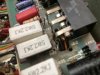
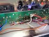
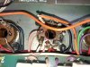
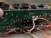
As some of you may have seen in one of my posts, my JCM900 MKIII 2100 has the board burnt near the High/Low power switch and the board has been drilled out. When looking at the bottom of the amp, the two prongs on the left of the High/Low switch are each wired to pin 3 of the middle power tube sockets (one wire from the switch to power tube 2, and one to power tube 3). I am not sure if this repair is making the switch operate backwards as the Low mode is louder than High mode. I only desire to use 100w mode so I am wondering how difficult it would be to either bypass the switch and make it just pentode operation or to remove the switch?

")