How is DSL401 grounded?

  • Thread starter stratfordade
  • Start date
  • This site may earn a commission from merchant affiliate links like Ebay, Amazon, and others.

stratfordade

Member
Joined
Feb 8, 2024
Messages
54
Reaction score
39
I'm chasing a slight hum problem on an otherwise fine DSL401.

This may seem a daft question, but how is the main PCB grounded? The power receptacle ground is bolted into chassis but I see no spade connector leads from any PCB terminal going to any point on chassis.

I'm suspicious of grounding because I'm measuring about 5 ohms between anywhere meant to be grounded (e.g. the ground ends of the hum reduction resistors for the EL84s, centre terminal of bias adjust connector) and that power connector ground. Why isn't everything tied down to chassis ground?

Had the PCB out before to change some caps, but I want to leave in for now while I complete some tests so can't check any ground tracks on other side of PCB to see what connects them up, but I will be getting board out later.

Thanks for any pointers!
 

Attachments

  • marshall_dsl401_dl40-60-02_v.6_sch.pdf
    269.7 KB · Views: 2

bfglp

Member
Joined
Jul 30, 2009
Messages
136
Reaction score
5
Should be at a stand-off bolt to a PCB trace, usually one by V1 some have multiple depending on year
 

stratfordade

Member
Joined
Feb 8, 2024
Messages
54
Reaction score
39
Thank you there are six small bolts going into standoffs supporting the PCB, but as board is still in I can’t see if they are ‘sandwiching’ ground tracks on other side onto the standoffs.

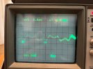
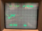
It’s very odd as I have that 5 ohm resistance between the ground of power receptacle and connections meant to be grounded. I’m also seeing very spikey 50Hz signal across speaker output even with amp on standby (first photo). The photo on right shows the hum I hear when the amp is off standby. It’s getting into power amp somehow - this is with all preamps V1-V3 removed.
 

Attachments

  • IMG_5363.jpeg
    IMG_5363.jpeg
    141.5 KB · Views: 2
  • IMG_5361.jpeg
    IMG_5361.jpeg
    121.8 KB · Views: 2
Last edited:

PelliX

Well-Known Member
Joined
Jun 16, 2020
Messages
7,394
Reaction score
14,930
It’s very odd as I have that 5 ohm resistance between the ground of power receptacle and connections meant to be grounded.

5 Ohms is within tolerance, I'd say. Is this excluding the resistance of your meter probes?

I’m also seeing very spikey 50Hz signal across speaker output even with amp turned off but power lead still inserted (first photo).

...of about 5mVpp. Given that the speaker jack is ground referenced to the chassis, as is the mains input, I wouldn't say that's very surprising. If you pop your scope probe on the chassis of adjacent gear or straight on the ground terminal of a socket on the same circuit, do you see the same thing more or less?
 

stratfordade

Member
Joined
Feb 8, 2024
Messages
54
Reaction score
39
Yes the 5 ohm excludes the 0.2 ohm lead resistance.

You are right about that mains noise being low level and present on another socket ground.

The amp is mysteriously ok now. Much quieter and no hum, so I think I’ll get board and and go over lots of joints in case something intermittent.

One thing I have found is that the input jack tip is not grounded with no jack inserted - the contacts are slightly apart so at least I can replace that while board is out, and uprate the preamp DC heater electrolytics which are only 6.3V. Will also let me check grounding as 5 ohm between parts meant to be grounded and power ground seems far too high.
 
Top