JCM 900 4100 DR DCV at pins 5 high

  • Thread starter KVH
  • Start date
  • This site may earn a commission from merchant affiliate links like Ebay, Amazon, and others.

KVH

Member
Joined
May 3, 2020
Messages
44
Reaction score
7
So this amp was plugged into a cabinet that had issues with the 16ohm input jack. Basically it was operated without a load.
One of the HT fuses was blown and the 1.5k grid stopper was cooked. Fuse replaced and new resistor in place. Input jack PCB on Cab re-soldered and now reads 13.6 ohms.
Pin 5 to ground on tubes 1 and 4 read 85vdc. Tubes 2 and 3 have the 1.5Ks mounted on PCB
and read the same. Adjusting bias pot lowers to 71V. This is with all power tubes out of amp. This amp was made just when Marshall was transitioning from EL34s to 5881s.
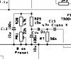
R31-34 are 1K
R28 is 22K
R2915K
I've read 42vdc to 56vdc is what I should be getting depending on which tubes it's set up for.
Where should I go from here?
Also on the EL34 schematic R28 is listed as 47k and VR1 as 22K but it's hard to read.
 

Attachments

  • R28etc.png
    R28etc.png
    12.7 KB · Views: 7

Pete Farrington

Well-Known Member
Joined
Jan 18, 2021
Messages
3,226
Reaction score
4,256
Location
Staffordshire UK
Yeah, reading the OP is like entering a parallel reality, if there’s +85VDC on the output valve control grids, then there’s a major breakdown of insulation, possibly conductive tracking from arcs.
As component references from the schematic are being used, note that the output valves are V4 to V7.
The output valve type that this amp uses needs to be noted.
https://www.thetubestore.com/lib/th...rshall-JCM900-Dualrev-100W-4100-Schematic.pdf
 
Last edited:
  • Like
Reactions: KVH

Spanngitter

Well-Known Member
Joined
Jan 22, 2019
Messages
515
Reaction score
563
Location
Upper Palatinate / Bavaria
Normally VR2 should be 47k Pot, if there is only a 22k you might have issues with R28=47k to get into range => you can also beef that up to 56k to get into range of valves..
BTW: OT primaries do measure OK?
 
  • Like
Reactions: KVH

66 Kicks

Active Member
Joined
Apr 15, 2019
Messages
117
Reaction score
108
You must have the tubes installed and the Standby switch closed in order to have the proper bias voltage. Set the bias voltage to "85vdc", install all of the tubes, power up and close the Standby switch (put it in the Play position). Now it should have the expected bias voltages.
 
  • Like
Reactions: KVH

Pete Farrington

Well-Known Member
Joined
Jan 18, 2021
Messages
3,226
Reaction score
4,256
Location
Staffordshire UK
ou must have the tubes installed and the Standby switch closed in order to have the proper bias voltage
Only the output valves are removed, so once the preamp valves have warmed up, their HT current should allow the bias circuit to charge.
Provided that the standby switch is closed, good call pointing that out :)
 
  • Like
Reactions: KVH

KVH

Member
Joined
May 3, 2020
Messages
44
Reaction score
7
So once I install output tubes that should bring down bias to normal range from 85 volts? Standby switch closed as in run or play correct? I do have a variac
so maybe I'll ease it up a bit while monitoring bias. I also have a bias probe that I made last year when I 1st worked on this amp. New filter caps and a few others.
Bias adjusted fine after new parts and worked until recently. Thanks all for your help.
 

66 Kicks

Active Member
Joined
Apr 15, 2019
Messages
117
Reaction score
108
Only the output valves are removed, so once the preamp valves have warmed up, their HT current should allow the bias circuit to charge.
Provided that the standby switch is closed, good call pointing that out :)
The bias voltage is not the same with only the preamp tubes installed, but it is close enough for a preliminary bias setting. After the output tubes are installed and the amp has settled, the final bias voltage can be set.
 
  • Like
Reactions: KVH

KVH

Member
Joined
May 3, 2020
Messages
44
Reaction score
7
Normally VR2 should be 47k Pot, if there is only a 22k you might have issues with R28=47k to get into range => you can also beef that up to 56k to get into range of valves..
BTW: OT primaries do measure OK?
So before I test under power I'll take your advice to check OT. I've discharged all voltage in caps. Can the OT be tested in circuit with an ohm meter? I checked the Secondary side between Green to Yellow, Green to Violet, and Green to Orange. I'm getting .1 to .3 ohms and I'm sure my leads are counting for the some of that so no I'm not a tech but that doesn't sound good.
 

Attachments

  • OT.jpg
    OT.jpg
    69.9 KB · Views: 2

Pete Farrington

Well-Known Member
Joined
Jan 18, 2021
Messages
3,226
Reaction score
4,256
Location
Staffordshire UK
A OT’s secondary is a few turns of comparatively thick wire, so its resistance will be low. Despite that, by the near magic of transformer action, an amp’s output signal appears across it.
 

KVH

Member
Joined
May 3, 2020
Messages
44
Reaction score
7
A OT’s secondary is a few turns of comparatively thick wire, so its resistance will be low. Despite that, by the near magic of transformer action, an amp’s output signal appears across it.
So if the OT is bad am I risking damage to the speaker cab if I do indeed reinstall tubes and test bias? As I mentioned b4 I'll be using a variac so low and slow like a nice brisket.
 

66 Kicks

Active Member
Joined
Apr 15, 2019
Messages
117
Reaction score
108
So if the OT is bad am I risking damage to the speaker cab if I do indeed reinstall tubes and test bias? As I mentioned b4 I'll be using a variac so low and slow like a nice brisket.
He is saying that the secondary readings are normal. What about the primary resistances?
 

KVH

Member
Joined
May 3, 2020
Messages
44
Reaction score
7
He is saying that the secondary readings are normal. What about the primary resistances?
Ok, White to Red is 33.5 ohms, White to Brown 16.7 ohms, Brown to Red 16.4 ohms.
 

Spanngitter

Well-Known Member
Joined
Jan 22, 2019
Messages
515
Reaction score
563
Location
Upper Palatinate / Bavaria
If an OT fails it usually fails on the primary side because of the thinner wire with thinner insulation. So far I haven't had an OT with bad secondaries, its one side which usually has an short somewhere or even goes open. Your readings are quite ok and normal, so set your Bias Voltage max negative, get your Power Tubes in and fire it up, then dial bias in.
Let it run idle for an hour under observation to catch any bias creeping, readjust and then run it with signal for an hour into a dummy load, then recheck bias.
If still ok => problem fixed.
 
  • Like
Reactions: KVH

Pete Farrington

Well-Known Member
Joined
Jan 18, 2021
Messages
3,226
Reaction score
4,256
Location
Staffordshire UK
If an OT fails it usually fails on the primary side because of the thinner wire with thinner insulation
Dunno about the thinner insulation hypothesis?
Failures in the primary seem more probably due to the reflected voltages being far higher, and due to it being exposed to DC fault current, eg when an output valve shorts, there’s a bias failure.
An open circuit secondary on the OT of an amp attempting to put out a high power signal being the ‘perfect storm’.

Given the info in the OP, it may be beneficial to emphasise that the VDC at pin 5 of the output valve sockets must be negative with respect to chassis 0V.
 

Spanngitter

Well-Known Member
Joined
Jan 22, 2019
Messages
515
Reaction score
563
Location
Upper Palatinate / Bavaria
Dunno about the thinner insulation hypothesis?

I once was told by a guy who built really excellent Transformers that (especially on enamel coated wire) a thicker wire (like AWG20) builds up a thicker layer then let's say an AWG 42. Would make sense to me as this emaille coating is applied to the hot wire and a thicker wire keeps the heat longer hence attracting a ticker enamel layer. :shrug:
 

Pete Farrington

Well-Known Member
Joined
Jan 18, 2021
Messages
3,226
Reaction score
4,256
Location
Staffordshire UK
a thicker wire (like AWG20) builds up a thicker layer then let's say an AWG 42. Would make sense to me as this emaille coating is applied to the hot wire and a thicker wire keeps the heat longer hence attracting a ticker enamel layer.
Thanks, that seems feasible!
 

cozmacozmy

Active Member
Joined
Apr 9, 2011
Messages
179
Reaction score
119
Location
West Michigan

Latest posts


Top