• We are looking to make improvements to the Classifieds! Help us determine what improvements we can make by filling out this classifieds survey. Your feedback is very appreciated and helpful!

    Take survey

JCM900 4100 high plate voltage! Any help

  • Thread starter saranden
  • Start date
  • This site may earn a commission from merchant affiliate links like Ebay, Amazon, and others.

saranden

Member
Joined
Feb 4, 2009
Messages
43
Reaction score
0
Location
UK
If this doesn't help I will try my hardest to get a picture..very difficult.

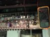
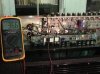
What is the definitive answer that tell you my amp is definitely an EL34 model?

Green wire comes from mains transformer pin 5, links to both capacitors and then to GN5 on pcb.
Cap 1
(+ post red) Red wire to JMP52C board RD2 to R5 and Blue wire to pcb BL3 to R23
(+ post yellow) Yellow wire to pcb YE3 to R35

Cap 2
Orange from output transformer goes to -post

Both + posts are linked:-
Red wire to pcb RD2 to pico fuse
Brown wire from output transformer
 

RussBert

Active Member
Joined
Apr 8, 2012
Messages
584
Reaction score
251
Location
connecticut

On page 1 you said you are getting 486v. Which is it? Is your meter good? Make sure the battery is fresh!

286vAc across the standby switch can't be right!! (and I realize that you're in the UK)

Still waiting for all the voltage readings from the power tube sockets...(after you check the battery in your meter, of course!)
 

saranden

Member
Joined
Feb 4, 2009
Messages
43
Reaction score
0
Location
UK
OK. Here's what I've done. While it was turned on and I was probing for voltages on V5, the amp started making a terrible rustling crackling sound, and stopped when I pressed pin 5, the green wire. Just to make sure, I jiggled the wire again, and sure enough it started up again, it sounded like I was amplifying through the glass of the tube. Anyhow, I read that you can tighten up the pins in the socket, so I did. Turned it back on and it sounded silent with no fault with the said connection. I had also made sure that the pairs of tubes were in 1-4 and 2-3. When I probed for plate voltage, it was 478V, so I did my calculation and got 36.6mV for bias. I plugged my octal bias probe and was reading 8mV!!!!
So from ther I was able to turn it up to reach 36.6mV easily. As it has been standing, it has slowly edged upwards by 1.3mV so I have rebiased to 36.6mV.
I have come to the conclusion that socket V5 is definitely faulty as I have to keep jiggling the valve to stop the crackling noise when it starts. None of the other valves do this at the socket. As it is now 3.00am, I think I should have some sleep. I will let you know what the voltages are at the pins 1-8 anyway.

V4 & V7
1. Linked with 8. 0dcv
2. 0dcV
3. 478dcV
4. 473dcV
5. -38dcV linked with pin 6 with resistor
6. -38dcV
7. 0dcV

V5 &V6

1. Linked with 8. 0dcv
2. 0dcV
3. 478dcV
4. 467dcV
5. -38dcV
6. 0 empty
7. 0dcV

Must get some sleep. Coz I'm feeling bleary eyed and that's a danger. I love what I have achieved so far with everyone's help. I'll speak later on today. Cheers
 

saranden

Member
Joined
Feb 4, 2009
Messages
43
Reaction score
0
Location
UK
here the Bias reading view. Im going to order 4 new octal sockets. do you think ceramic is better?
sorry the picture is up-side-down!!!!!
36.6mV
 

Attachments

  • bias.jpg
    bias.jpg
    95.4 KB · Views: 22

saranden

Member
Joined
Feb 4, 2009
Messages
43
Reaction score
0
Location
UK
sorry RussBert. with the loose tubes I was getting erratic reading. Now i realize that, i will remedy it. The readings I have listed above, are made after the amp was turned on for about an hour, fully warmed up. I checked and double checked.
Hope that makes a bit more sense. I swapped the tubes to pairs. whereas before they weren't. 2 Chelmer EL34A's in 1-4 and 2 Electrons in 2-3. I am going to buy another matching quad to have as backup.
 

SmokestackElRopo

Well-Known Member
Joined
Jan 7, 2008
Messages
530
Reaction score
288
So good to see everybody concerned working well together, Welcome Jon good of you to show up, we miss your prescence.:cheers:
 

RickyLee

Well-Known Member
VIP Member
Joined
May 22, 2010
Messages
10,297
Reaction score
3,711
Location
SoCal U.S.A.
V4 & V7
1. Linked with 8. 0dcv
2. 0dcV
3. 478dcV
4. 473dcV
5. -38dcV linked with pin 6 with resistor
6. -38dcV
7. 0dcV

V5 &V6

1. Linked with 8. 0dcv
2. 0dcV
3. 478dcV
4. 467dcV
5. -38dcV
6. 0 empty
7. 0dcV

You already have a few seasoned and highly experienced techs helping you here. But I am curious to why the power valve sockets are wired this way?

On V5,V6 you have pin 6 as empty, but on V4,V7 you the negative bias voltage for the control grids on both pins 5 & 6. Is it just a tie point but the screen grid resistor is floating on one leg or coming off the PCB?

And V5,V6 pin 4 is much lower (467V) on those sockets.
 

plexifier

Active Member
Joined
Aug 13, 2011
Messages
515
Reaction score
188
Location
Iowa
...On V5,V6 you have pin 6 as empty, but on V4,V7 you the negative bias voltage for the control grids on both pins 5 & 6. Is it just a tie point but the screen grid resistor is floating on one leg or coming off the PCB?

And V5,V6 pin 4 is much lower (467V) on those sockets.
Good points Ricky. :)

The screen resistors (which are commonly mounted across pins 6 and 4 in older amps are PCB mounted so that's fine). Of more concern is the voltage difference on pin 4 of the two pairs. It's only 6 volts and may be caused by how or when those were measured (how long the amp was out of standby, etc.). That may be worth checking on though.

It is odd to have grid resistors mounted across pins 6 and 5, especially on only two of the tubes but maybe that's stock on a 900. ? Also, the schematic shows single 1k5's on V4 and V6 but additional 1k5's going to V5 and V7, which doesn't jive with saranden's physical descriptions. Either way, it's odd but not critical for bias voltage.

saranden: How's it going? The bad part is when all is said and done, you'll still have a JCM900! (sorry, couldn't resist) ;)
 

RickyLee

Well-Known Member
VIP Member
Joined
May 22, 2010
Messages
10,297
Reaction score
3,711
Location
SoCal U.S.A.
Good points Ricky. :)

The screen resistors (which are commonly mounted across pins 6 and 4 in older amps are PCB mounted so that's fine). Of more concern is the voltage difference on pin 4 of the two pairs. It's only 6 volts and may be caused by how or when those were measured (how long the amp was out of standby, etc.). That may be worth checking on though.

It is odd to have grid resistors mounted across pins 6 and 5, especially on only two of the tubes but maybe that's stock on a 900. ? Also, the schematic shows single 1k5's on V4 and V6 but additional 1k5's going to V5 and V7, which doesn't jive with saranden's physical descriptions. Either way, it's odd but not critical for bias voltage.

saranden: How's it going? The bad part is when all is said and done, you'll still have a JCM900! (sorry, couldn't resist) ;)

I am now remembering seeing the 100W SL-X schematic having four 1.5K grid leaks, with the value of 1.5K on two sockets, BUT the other two sockets have their 1.5K IN SERIES with those other two 1.5K for a 3K total grid leak value on two sockets.
 

saranden

Member
Joined
Feb 4, 2009
Messages
43
Reaction score
0
Location
UK
I've just received my 4 new EL34 sockets and will install them. It is really of no use asking me anything technical. I have took my guidance from all of the brilliant techs above, including earlier on the "check the socket for arcing". I had the amp running for an hour before doing final reading and the bias was ticking over perfectly...going up slightly when playing hard and ticking over on normal playing. I am well chuffed. Sounds beautiful compared to the solid state amps I have.

If you would like to ask me where R*** goes on the pcb or what is the reading of R*** I can tell you but ask me in straight forward language. I don't know if the amp is wired up unusually but hey..still works great. What wattage do you think the resistor is which is soldered on the tube socket. Do you think it's 1/2W?
 
Last edited:

RickyLee

Well-Known Member
VIP Member
Joined
May 22, 2010
Messages
10,297
Reaction score
3,711
Location
SoCal U.S.A.
I have my terminology mixed up again :D

Those 1.5K resistors I mentioned above are grid swampers/stoppers. Sorry about that.

As for the wattage? Being it is a JCM900, they might be 1/4W. Marshall started using the 1/4W resistors in place of the 1/2W somewhere around 1988/89. This is only in regards for most of the low powered parts of the circuitry.

As for the amp being wired up unusually? Probably not. That is what I was talking about in my other post. The 900's were a bit different on the layout than the preceding Marshall amps. You will see the affects of "cost cutting" as well as simplified production methods in the 900 series compared to the 800 series Marshalls.
 

Jonathan Wilder

Well-Known Member
Joined
Oct 12, 2009
Messages
6,163
Reaction score
747
Location
Greenville, SC
It is odd to have grid resistors mounted across pins 6 and 5, especially on only two of the tubes but maybe that's stock on a 900. ?

OMG!!! Which grid!? Could this be a big problem!?!?!? I mean...I read somewhere that grids should only be connected to certain pins and pins 6 & 5 were not them, and my amp is totally wired that way!!! What should I do!?!? OMG my parents are gonna fuckin' kill me.
 

plexifier

Active Member
Joined
Aug 13, 2011
Messages
515
Reaction score
188
Location
Iowa
OMG!!! Which grid!? Could this be a big problem!?!?!?...
If you read my post, I was talking about the control grid (pin 5) and the 1k5 grid stopper resistors. Pin 6 has no internal connection in EL34's and the screen grid resistors aren't mounted on the tube sockets in this amp.

What is the "big problem"? Please explain.
 

fastdave

Member
Joined
Jan 17, 2011
Messages
91
Reaction score
19
Location
Fife,Scotland
Thank goodness someone who knew his stuff has come (back) on board.
Welcome, Sir Wilder - you have been of much help to me.
I discovered my factory 5881 amp was modified to take el34's, and had to modify the divider circuit with 3 22k's in series in place of the 56k to get the voltage right! (It was all I had - does the job!).
The statement made about the valves not pulling enough current was a bit of a cracker - I was going to come in at that point, - I read on and there you were!
Incidentally, I found it just as easy to insert my mA meter rather than fuss about with 1 ohm resistors, since I was disconnecting anyway, and I was cautious about the leads.
I'm sure this guy has been led by the hand so far, but it might have been worth recommending your series of lectures (basic circuitry), cos he disny have a clue.
Kindest regards,
Dave.
 

saranden

Member
Joined
Feb 4, 2009
Messages
43
Reaction score
0
Location
UK
Geez ah break Fastdave. I'd loved to have gone to Uni, but circumstances you know.
I'm a diy'er with common, and you know, some people have a lot of common but no sense!!!
I'm a quick learner especially when it's a subject that you've loved since you were knee high. It never gets boring.

I'm grateful to engineers like Plexifier and Wilder Amplification who are willing to educate us beginners and lead us by the hand. We all started somewhere usually at college, only hey, some of us are in our 60's and need something to stimulate the grey cells. I have also had a comment, not on this forum, to leave it to the people who know....Now that's facetious!...... Hey it's fixed, and you guys did it, I was just the mobile hand with the solder station and a bit of know how....
THANKS ALL..BYE
 

saranden

Member
Joined
Feb 4, 2009
Messages
43
Reaction score
0
Location
UK
Good points Ricky. :)

The screen resistors (which are commonly mounted across pins 6 and 4 in older amps are PCB mounted so that's fine). Of more concern is the voltage difference on pin 4 of the two pairs. It's only 6 volts and may be caused by how or when those were measured (how long the amp was out of standby, etc.). That may be worth checking on though.

It is odd to have grid resistors mounted across pins 6 and 5, especially on only two of the tubes but maybe that's stock on a 900. ? Also, the schematic shows single 1k5's on V4 and V6 but additional 1k5's going to V5 and V7, which doesn't jive with saranden's physical descriptions. Either way, it's odd but not critical for bias voltage.

saranden: How's it going? The bad part is when all is said and done, you'll still have a JCM900! (sorry, couldn't resist) ;)
It went really well, I took all the advice I was given, decided to change the valve sockets for ceramic ones which made it look a little more sophisticated! However, one fault I could not fix is, when you flick the switch from 100w to 50w on the back of amp switch, the amp will not work apart from a massive hum like its imminently going to explode, so I don't know what to do there.
Other than that, it sounds great....I suppose I will only be able to sell it for spares or repair with a fault like that. I've bought a Jvm410c and I think it actually sounds way better.
 

Latest posts


Top