• We are looking to make improvements to the Classifieds! Help us determine what improvements we can make by filling out this classifieds survey. Your feedback is very appreciated and helpful!

    Take survey

JCM900 4100 high plate voltage! Any help

  • Thread starter saranden
  • Start date
  • This site may earn a commission from merchant affiliate links like Ebay, Amazon, and others.

saranden

Member
Joined
Feb 4, 2009
Messages
43
Reaction score
0
Location
UK
Hello everyone.
I bought a Marshall JCM900 4100 for repair. The guy I bought it off, told me that it just faded out.. I thought great.. New tubes and I'm away!
One of the pins was missing off one of the EL34A's so I bought four new tubes.
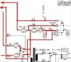
HOWEVER.....The pico fuse had been snipped on one end off of the pcb, I replaced the pico as it was open circuit, I replaced R31-R434 all 1K 5W resistors, and R35 had been removed, so I replaced it with 100R 5w all wire wound. I also upgraded C15 to a 1000V instead of 250V as I read these often fail because of their low voltage Wonders how it faded out the day before I bought it, perhaps he meant it faded out long ago before he started fiddling about with it!

Anyway

I then turned the amp on let it warm up then measured the plate voltage.
It was 598V. After reading loads of threads about plate voltage, I assumed it would be about 460V - 480V. I decided to install the new tubes and measure the plate voltage again also assuming it would drop a little.. It didn't.

When I read the bias measurement, I could not get it above 2.9mv when according to the plate voltage my bias should be around 29.2mv. I expected to start setting at above 37mv and a 470V plate voltage.

Anyway...there's my problem, I am reading nigh on 600V from the transformer and at the plate voltage, also still no audio output! Could anyone help me with this repair. Should I consider that the transformer or caps are faulty? What voltage should I expect from the transformer? Also when I selected low mode output on the back of the amp, it started humming quite loud and the tubes were quite warm, so I immediately returned it to high mode and it was back to silence and normal glowing tubes.
 
Last edited:

RussBert

Active Member
Joined
Apr 8, 2012
Messages
584
Reaction score
251
Location
connecticut
one of the pins was "missing" ??

The tubes are not drawing any current. Suspect some bad soldering on the components you just installed, or a burned/lifted trace.
 

saranden

Member
Joined
Feb 4, 2009
Messages
43
Reaction score
0
Location
UK
Thanks RussBert, I'll check for burnt traces and re-solder suspect joints. I thought I'd check to see if I'm producing any audio through the pre-amp by hooking up the line out to another amp input, it is not producing any audio through line out either. Would this substantiate what you think?

I checked all my joints, all are good. Resoldered a lot of them just to make sure. I traced the tracks across the board and all of them are good.

I tested all voltages from the transformer, and all are almost exactly as the datasheet for the 290JX transformer. Why is there 600v at the plate voltage.

I only know what I know in electronics from what I have learned over the years.
It would be helpful if I was told in really simple terms, like when you first started to learn about electronics, and loved it! I can use the tester efficiently, and can follow the schematic easily. Incidentally, this amp was built with EL34A's the wiring looks as straight from factory, pin 1-8 are joined on the tube the serial number also starts with Z which I am led to believe is when Marshall JCM900 4100 used the EL34A.
 
Last edited:

saranden

Member
Joined
Feb 4, 2009
Messages
43
Reaction score
0
Location
UK
I've checked all traces on pcb pc0112. All are good. My newly soldered R31-43 are all good joints.
I measured all of the voltages coming from the transformer.
1-2 =125v
3-4 =125v
5-6 =7.3v
5-7 =3.6v
8-9 =387
White - black 23v
White - black 23v
Compared to the datasheet for this transformer, this is pretty spot on.
What would be the next step, if I am getting the power from the transformer.

I find it difficult to understand why there is 600v at the plate voltage.....

Please remember that you have to explain to me in simple terms like when you went to college and needed to be told and shown. I can use my tester efficiently so I can test between two points and give anyone the reading. I always discharge after unplugging as well. When you say not drawing current, I don't understand what you mean, but if you ask me to test between two points I do.
I can follow the schematic easily up the tubes, I find the tubes bit a little bit confusing! Easier to follow the TDA's in the solid state amps!!
 

saranden

Member
Joined
Feb 4, 2009
Messages
43
Reaction score
0
Location
UK
Ok. I tested the resistor I'd replaced(which was absent when I bought it) R35 with 100R 5w wire wound, and it had blown leaving open circuit. I replaced it, turned the Amp on and it quickly fizzled out again.
What next?
 

saranden

Member
Joined
Feb 4, 2009
Messages
43
Reaction score
0
Location
UK
Volts at the power tube with the faulty resistor are:
Output tube voltages.
1. 0
2. 0
3. 614
4. -0
5. -032
6. -032
7. 0
8. 0
 
Last edited:

RussBert

Active Member
Joined
Apr 8, 2012
Messages
584
Reaction score
251
Location
connecticut
That's odd...


pins 1 & 8 should be tied together fo EL-34's. Is your amp designed to use EL-34's?

Pins 4 & 6 are linked by the 1k 5w screen resistor and should show close to plate voltage (pin 3)

I don't know what R35's purpose is, and I don't have a schematic. Does your amp have a choke?


Again, the reason the pV is so high is because the tubes are not conducting.
 

saranden

Member
Joined
Feb 4, 2009
Messages
43
Reaction score
0
Location
UK
I picked up the schematic from here: Marshall Amps Info & Schematics
It has schematics for 5881 and EL34A models. Mine is the 4100 100W model EL34A tubes

Pin 1-8 are tied. As it had 2k2 4w resistors R31-34 which looked to me as though they had never been soldered/unsoldered since new, and other resistors are as the schematic for EL34A's, I would say yes it is standard EL34A model.

You asked if my amp has a choke. Tell me what to look for and I'll tell you.
 
Last edited:

saranden

Member
Joined
Feb 4, 2009
Messages
43
Reaction score
0
Location
UK
Does a choke look like a small transformer on the pcb. There isn't one
 
Last edited:

plexifier

Active Member
Joined
Aug 13, 2011
Messages
515
Reaction score
188
Location
Iowa
Volts at the power tube with the faulty resistor are...
Were those voltages from just one socket or do all four read the same?

Were you in high or low power mode when you got 0 volts on pin 4?

If it was in low power, the switch could be bad or R31 through R34 or their connections are bad (not likely that all 4 are bad).

If it was in high power mode, you have a problem somewhere in the screen voltage supply (near fuse F4, R35, R30, screen filter caps, etc.).

It doesn't have a choke.
 

saranden

Member
Joined
Feb 4, 2009
Messages
43
Reaction score
0
Location
UK
Ok. It was in high power. When I switched to low power, it was making a humm through the speaker and smelled a bit hot. I turned it off and switched back to high power. All the tubes are lighting up. No sound from pre amp. The voltages were from 1 socket, the one nearest the screen capacitors.

R35 has gone open circuit, I have replaced it twice and both times when the amp was turned on...it fizzled..To open circuit. The pico fuse is good. R30 reads 22.7k
The high low switch operates ok with no short between contacts when switched between high and low.
All R31-34 are good, with perfect solder joints and I tested from solder point to next point and they are all good.

I think one of the screen filter caps is faulty.
I disconnected the wires and measured with the capacitance meter.
The one with the red, blue and yellow wire measured 50uF and 50uF
The one with the red and brown wire reads open and open. Suspect this to be faulty.
So would this faulty cap cause R35 to keep blowing?
The faulty cap comes before the pico fuse and the good on comes after R35
 
Last edited:

plexifier

Active Member
Joined
Aug 13, 2011
Messages
515
Reaction score
188
Location
Iowa
The filter cap that reads open is definitely bad and yes, that could cause R35 to burn up, although I'm surprised it doesn't blow the fuse (F4).

Something else is bad if a preamp line out or effects send doesn't work though. I'm not very familiar with that amp (just looking at schematics). Try different preamp tubes first.
 

saranden

Member
Joined
Feb 4, 2009
Messages
43
Reaction score
0
Location
UK
I will try 3 good ECC83's tomorrow and see if the pre amp produces any audio. I will check the LT power supply in the pre amp to make sure that is +15v -15v.

I am going to order the capacitors from Marshall here in the UK. They are very good, I emailed a guy called Nick Fisher At Marshall Amplification plc for some TDA7293 modules as the ones I had had exploded burning the headers etc. he got back to me the same day and said "I can send them next day for £12 each + £12 postage". Next day, there they were....superb.
So I've sent him a request for availability and I guess they'll only be about £7 each.

When they come, I'll replace both of them, replace R35 then see where we go from there.
 

saranden

Member
Joined
Feb 4, 2009
Messages
43
Reaction score
0
Location
UK
So I've replaced the pair of filter caps. I replaced R35 with new 100R 5w WW.
I installed 3 good ECC83's in and turned on the power to standby. Plugged my headphones in to Effects return. Has audio. Line Output. Recording Compensated and Direct. No audio

Switched from standby to on, R35 fizzled out again, pico fuse did not blow. It is the correct rating pico fuse. It takes about 6-8 seconds for the resistor to blow, with or without the new tubes in.

High output.
Output tube voltages. With blown R35
V4 & V7.
1 . 0. (low output. 0v)
2. 0. (low output. 0v)
3. 614. (low output 373v)
4. -0. (low output 373v)
5. -032 linked to pin 6 with Resistor. Low output. -48v
6. -032. Low output. -48v
7. 0
8 Gnd
V5 & V6
All pins have same voltage except
5. -32v. Low output -48v
6. Empty
 
Last edited:

plexifier

Active Member
Joined
Aug 13, 2011
Messages
515
Reaction score
188
Location
Iowa
Just some general advice but hopefully this will help:

Something is pulling way too much current through R35 (obviously).

Does R35 burn up with none of the tubes installed? If so, there must be a short somewhere in the B+ line. If it only burns with tubes in, one of the tubes is probably bad or a tube socket may be arcing when the tubes start to pull current.

The fuse should be 3A (probably slow-blow).

I would leave all tubes out and drain the filter caps. Carefully check the power tube sockets (or PCB mounts) for carbon traces or burn marks. If a power tube has failed in the past, there could be a short between pin holders or PCB traces.

Check the B+ line downstream from R35, looking for shorts to other wires, PCB traces, etc. Basically, see if there is possible contact between it and something it shouldn't be touching. Use a meter to check for continuity between areas that shouldn't have any, etc.
 

plexifier

Active Member
Joined
Aug 13, 2011
Messages
515
Reaction score
188
Location
Iowa
What difference will it make if I re-install the 2K2 4W screen resistors instead of the 1K 5W.
No difference at this point because you're not even getting voltage to the screens yet.

All pin 5's should have the same NEGATIVE DC voltage.

Can you post some pictures? (power tube sockets, filter cap wiring, etc.)
 

Guitar-Rocker

Well-Known Member
Joined
Mar 5, 2012
Messages
3,251
Reaction score
3,168
Location
Estero, Florida formerly from Indianapolis
Just some general advice but hopefully this will help:

Something is pulling way too much current through R35 (obviously).

Does R35 burn up with none of the tubes installed? If so, there must be a short somewhere in the B+ line. If it only burns with tubes in, one of the tubes is probably bad or a tube socket may be arcing when the tubes start to pull current.

The fuse should be 3A (probably slow-blow).

I would leave all tubes out and drain the filter caps. Carefully check the power tube sockets (or PCB mounts) for carbon traces or burn marks. If a power tube has failed in the past, there could be a short between pin holders or PCB traces.

Check the B+ line downstream from R35, looking for shorts to other wires, PCB traces, etc. Basically, see if there is possible contact between it and something it shouldn't be touching. Use a meter to check for continuity between areas that shouldn't have any, etc.


A plus +1 there, very sound advice before something else self destructs. There has to be a short, track mark or something you can identify, without tubes in.
 

saranden

Member
Joined
Feb 4, 2009
Messages
43
Reaction score
0
Location
UK
Hello Plexifier. Thank you for your help, I think you may have read early on in this thread that I am very good at following instruction and I can read the schematic really well (except for the tube sockets on the diagram) and as a hobbyist you will just have to tell me where the B+ line is. I assumed you mean the line on the schematic that goes through the pico, R35,R30, down to the filters etc.....
I found no short to the chassis.
The resistor blows with tubes in or out
I checked for shorts by probing in to the tube sockets. Pins 8+1 are linked so they are short but the are also shorted to 7+2, so 7,8,1+2 are all shorted to chassis and each other.
I have to go to hospital tomorrow, and also I have to take photo's and upload to the computer before I can post to you as I am doing all of this from an iPad 1 with no camera. But I'll post images.
If you ask me where to check voltages from the schematic, I'll know exactly where you mean, and I'll do it. The 1K5 resistor that is across pins 5+6 on V7 looks a bit heat damaged but it still reads 1K5 ohms.
 

plexifier

Active Member
Joined
Aug 13, 2011
Messages
515
Reaction score
188
Location
Iowa
...you will just have to tell me where the B+ line is...
The B+ path (labeled "HT" on the schematic) will start at the power transformer and go through the standby switch, then to the rectifier diodes (or bridge rectifier component) then branches to filter caps, OT center tap, screens, preamp plates, etc.

It goes through the OT to the power tube plates (pin 3) and also to the screens (pin 4). It also branches off to the PI and preamp tube plates (ECC83 tubes - pins 1 and 6).

However, the problem is most likely in the screens path (between R35 through the power mode switch (SW2a + SW2b) through R31, R32, R33, R34 and on to the screens). NOTE: I'm not positive about this. It's just most likely.

Below is an image marking part of these paths. It's from the top-right of page 2 of this schematic:
http://www.drtube.com/schematics/marshall/4100-60-02-iss14.pdf

The power tube pin "shorts" you mentioned are normal.

...
 

Attachments

  • ht.jpg
    ht.jpg
    26.4 KB · Views: 36

Latest posts


Top