JMP: popping, crackling noise and volume drop

  • Thread starter LPman
  • Start date
  • This site may earn a commission from merchant affiliate links like Ebay, Amazon, and others.

LPman

Well-Known Member
Joined
Apr 3, 2016
Messages
242
Reaction score
437
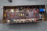
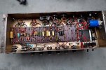
It's an old JMP amp. After playing for 30 mins at very high volume, the amp starts acting up. Volume is fading out, than crackling and popping noises appear. When I give a small knock with a pencil at the V1 preamp tube, the popping stops and sound comes back. Then after playing for 5 mins it starts again. The next day, it's the same - the amp is good for half an hour than it craps out. Tried changing V1 tubes, cleaning the V1 socket but no luck.

Before this problem started, I brought the amp to my tech and we modified the preamp plate voltage by bypassing one of the 10K dropping resistors that are next to the two bias filter caps (as it is on factory 2204's - only one 10k resistor). After that, the PI tube voltage increased to 340 V. My tech said that it shouldn't be a problem. Could this somehow be the culprit of V1 acting up suddenly or no correlation? Any ideas what to look for next?
 

XTRXTR

Well-Known Member
Joined
Feb 14, 2021
Messages
1,383
Reaction score
1,789
Location
Some City, USA
Is the 340 VDC on the pins 1 and 6 OR the voltage feeding the 82k and 100k load resistors of the PI? 340 on the pins would be bad should be around 250-255 range.
 

LPman

Well-Known Member
Joined
Apr 3, 2016
Messages
242
Reaction score
437
Is the 340 VDC on the pins 1 and 6 OR the voltage feeding the 82k and 100k load resistors of the PI? 340 on the pins would be bad should be around 250-255 range.

The tech said that 12ax7 tubes are rated at 300 - 330 VDC max so 340 VDC (when the volume is up it goes down to around 325) should be OK if I can live with maybe a little shortened life on the PI tube. V1 and V2 were measured at around 250.

Is this correct info or should I tell him to redo this mod?
 

PelliX

Well-Known Member
Joined
Jun 16, 2020
Messages
7,285
Reaction score
14,758
Back to your tech to check his soldering

BTW arcing EL34 sockets between pin 3 and 2 do this - so worth checking!

Agree with this ^

Why would you want to raise the voltage on the PI that much? Pushing components to their max will of course shorten their life - not a bad thing per se, but I wouldn't want to gig it like that. You mention "very high volumes", which leads me to believe this might a live situation?
 

LPman

Well-Known Member
Joined
Apr 3, 2016
Messages
242
Reaction score
437
Agree with this ^

Why would you want to raise the voltage on the PI that much? Pushing components to their max will of course shorten their life - not a bad thing per se, but I wouldn't want to gig it like that. You mention "very high volumes", which leads me to believe this might a live situation?

We simply turned the amp into a later 2204 by bypassing one of the 10k dropping resistors. This is stock configuration on 50w 2204 amps so nothing unusual. My amp is a '69 but has '74 PT and '74 OT so my plate voltage is lower than if it would be stock. On lower plate voltage JMPs it's a popular mod to increase the preamp voltage by removing one 10k resistor in order to tighten up the character of the amp.
 

Pete Farrington

Well-Known Member
Joined
Jan 18, 2021
Messages
3,241
Reaction score
4,272
Location
Staffordshire UK
Could this somehow be the culprit of V1 acting up suddenly or no correlation?
Almost certainly there’s no correlation.
The tech said that 12ax7 tubes are rated at 300 - 330 VDC max so 340 VDC (when the volume is up it goes down to around 325) should be OK
340V will be the HT supply node voltage for V3.
The anodes can never get anywhere near that, due to the 82k and100k anode load resistors, and the 220k grid leak resistors they’re driving.
Plus it’s the limit is in regard of the anode to cathode voltage, and the cathode voltage will be around 20 to 30V.
All in all, the valve in V3 has a pretty easy life, its operating conditions are not in the least bit arduous.
 
Last edited:

LPman

Well-Known Member
Joined
Apr 3, 2016
Messages
242
Reaction score
437
Well, we found the culprit. It was two 100K preamp resistors (V1 and V2). Both were original old '69 components. See the pic, I marked them with red.

THE PROBLEM: so the amp behaves steady as it should now, but it sounds a little different. A little thinner, not as punchy and tight. How come? We put in perfectly good 100k (measured) resistors that my tech had in his old stock drawer. He said that the amperage might be different but it doesn't have an impact on sound. Is that correct?

So why does my amp sound different now after that two resistor change? It's not my ears because I have a recording setup with a mic placement that has not been moved from my cab. The tonal change is very evident on the recording I made before and after with my usual settings.
 

Attachments

  • jmp2b.jpg
    jmp2b.jpg
    1,011.3 KB · Views: 178

Spanngitter

Well-Known Member
Joined
Jan 22, 2019
Messages
515
Reaction score
563
Location
Upper Palatinate / Bavaria
Maybe bc the old resistors had drifted and therefore differ from the stock 100k? Did you measure resistors before replacement and verify voltages?
Also, this am had several mods and repairs done to it andthere Is very sloppy soldering visible at some of the turrets so it might be still not in a good working order.
 

PelliX

Well-Known Member
Joined
Jun 16, 2020
Messages
7,285
Reaction score
14,758
He said that the amperage might be different but it doesn't have an impact on sound. Is that correct?

Resistors don't actually have an amperage rating, rather a resistance and wattage; those appear to be "standard" 1/4 (or 0.25) W. Replacing the resistors, as @Spanngitter pointed out, may have an effect on your tone, but if they have the correct resistance the amp will sound as it "should". I agree with him on the turrents, too - could do with a bit of touching up there, honestly. Also, why install old resistors? If you're replacing them anyway, put in new ones and (likely) forget about them for a substantial part of the remainder of your life... :)
 

jgab

Well-Known Member
Joined
Feb 1, 2009
Messages
1,055
Reaction score
429
Location
British Columbia Canada
Did he put in a couple Iskra 100K resistors? Is that what you mean by "his old stock drawer"?

You can buy new Iskra 100K resistors on ebay. That's what I would do, unless the resistors from the tech were indeed new (unused) Iskra resistors.

Do you have a photo of the replacement resistors in circuit? Also, as mentioned above, do you have any measurements of the resistors?
 

jgab

Well-Known Member
Joined
Feb 1, 2009
Messages
1,055
Reaction score
429
Location
British Columbia Canada
Before this problem started, I brought the amp to my tech and we modified the preamp plate voltage by bypassing one of the 10K dropping resistors that are next to the two bias filter caps (as it is on factory 2204's - only one 10k resistor).
I don't know why you would want to do this?

For some reason Marshall made changes and increased the screen supply, which resulted in too high of plate voltages to the preamp section. It is stupid that they only used one 10K dropper before the PI after this change. If you look at the 1981 specs on the 2204 and 2203, the plate voltages of the preamp tubes were significantly lower because of the lower incoming screen supply. They didn't compensate for this on my 2204 amps (mid 80's models with ~460vdc screens) and my preamp voltages were way too high. When I added a second droppers to my 2204 amp, it brought the plate voltages to the 1981 2204 specs and my amp/s have never sounded better. It really sweeted up the tone.

Running those high preamp voltages is not a mod I would be chasing, unless you don't the classic clear Marshall grind of the late 70's/early 80's.
 

LPman

Well-Known Member
Joined
Apr 3, 2016
Messages
242
Reaction score
437
We measured the resistors before putting them in the amp and after soldering too, they measured at 100K (+/- 2K) so they were good. I chose older ones that looked similar to the original ones in my amp out of a big bunch of resistors so that they don't look so out of place like some of those bright blue caps.

As I stated the amp is set up as a 2204, it is more usable for me this way compared to its original 4-holer form. The PT and OT are from a '74 JMP. In the 70s, plate voltage was a bit lower (360-400 VDC) than before and after so we compensated this by increasing the preamp voltage. It's a great sounding amp, it only puts out about 40 watts though.
 
Last edited:

LPman

Well-Known Member
Joined
Apr 3, 2016
Messages
242
Reaction score
437
When we measured those two old resistors, they were all over the place, jumping up as high as 150-170K in value while poking around their wires. Could the higher K ohm value of those faulty old ones be the reason for the fatter, punchier response of the amp? With the old ones the amp sounded better - at least for those 15-20 mins before the volume drops and crackling sounds started.

Should I change them to 150K to get back that tone?
 

neikeel

Well-Known Member
Joined
Feb 12, 2014
Messages
8,459
Reaction score
9,624
The originals were Iskra 100k, generally pretty stable and sound good. I have had to replace V1 plate resistors of that type that have gone open circuit in more than a couple of amps. I'm surprised the cathode follower anode resistor on V2 socket does not fail more often. I have also found that a lot of amps with cc resistors there that have drifted up (110k to 120k) do sound fatter.
I suspect in your case that you raised the preamp voltages by bypassing that dropper between screens and PI which will have given a little more clarity (thinner??) but having the original updrifted plate resistors counteracted that.
Higher plate resistors will give you a little more compression (and perceived gain) by lowering plate voltages. If you look at some high gain mods the plate resistors (amongst other things) are as high as 220k for an ECC83.
Easiest thing to try is to remove the bypass link to get V1 voltages where they were before the resistor change.
Of course you may prefer higher PI voltages and lower V1 and cathode follower voltages in which case, yes, put your link back and try a 120-150k resistor on cathode follower and v1b plate.
The cathode follower is probably the one: I was building a 45/100 for someone and was working late at night, picked up a 300k resistor and put on socket. Amp had loads of grind and gain and compression. Still replaced it with correct type to complete testing and ship it out but it give you and idea.
 

XTRXTR

Well-Known Member
Joined
Feb 14, 2021
Messages
1,383
Reaction score
1,789
Location
Some City, USA
The reason it was popping was the open and closing of the resistors that had drifted and got hot and cracked. I agree if you replace the 100k resistors with 120k to 150k instead it should sound like it was but not cracking and popping.
 

LPman

Well-Known Member
Joined
Apr 3, 2016
Messages
242
Reaction score
437
The originals were Iskra 100k, generally pretty stable and sound good. I have had to replace V1 plate resistors of that type that have gone open circuit in more than a couple of amps. I'm surprised the cathode follower anode resistor on V2 socket does not fail more often. I have also found that a lot of amps with cc resistors there that have drifted up (110k to 120k) do sound fatter.
I suspect in your case that you raised the preamp voltages by bypassing that dropper between screens and PI which will have given a little more clarity (thinner??) but having the original updrifted plate resistors counteracted that.
Higher plate resistors will give you a little more compression (and perceived gain) by lowering plate voltages. If you look at some high gain mods the plate resistors (amongst other things) are as high as 220k for an ECC83.
Easiest thing to try is to remove the bypass link to get V1 voltages where they were before the resistor change.
Of course you may prefer higher PI voltages and lower V1 and cathode follower voltages in which case, yes, put your link back and try a 120-150k resistor on cathode follower and v1b plate.
The cathode follower is probably the one: I was building a 45/100 for someone and was working late at night, picked up a 300k resistor and put on socket. Amp had loads of grind and gain and compression. Still replaced it with correct type to complete testing and ship it out but it give you and idea.

Many thanks for the great infos, all makes sense. I'm just learning my way around in these amps by observing what my tech is doing and reading the forums so this comes really handy. I'll try the recommended tweakings with the V1b, cathode follower and dropping resistors separately and record the amp in each of the configurations. Fascinating how such small variations can have an audible effect on tone.

I just have to find the sweet spot of this amp with a bit more experimenting.
 

william vogel

Well-Known Member
Joined
Dec 18, 2016
Messages
1,337
Reaction score
1,875
Put 180k plate load resistors in V1 and see if the amp gets it’s old character back. Or 150k. The important thing to restore it’s characteristic is to put back what was removed even though they were defective. The original 100k value is the correct value but for your case it changed the amp to be less favorable to your ear and unless you’re okay with adapting to the “new” sound, restore it to old sound hopefully without the noises.
 

LPman

Well-Known Member
Joined
Apr 3, 2016
Messages
242
Reaction score
437
It's a very interesting issue because after we replaced the two faulty V1 100K resistors, the problem still keeps coming back. Playing for half an hour with my usual settings (very high master) and then the V1 starts acting up. Volume and gain drops, crackling noise, I tap on the tube and it's good for another 5 min then starts again. Does it with every preamp tube and I've tried about a dozen one.

So I opened up the amp, turned it on, cranked the master and started tapping on all of the caps, resistors and solder joints in the amp with a plastic pen. One of the old 22n Mustards (V1 cathode cap?) has an amplified thud when I tap on it (I marked that cap on the pic below) while all of the other resistors and caps are noiseless. Can this Mustard cap cause all of my problem or is this normal?
 

Attachments

  • chassis2c.jpg
    chassis2c.jpg
    942.6 KB · Views: 27
Last edited:

XTRXTR

Well-Known Member
Joined
Feb 14, 2021
Messages
1,383
Reaction score
1,789
Location
Some City, USA
I am confused on the wiring of the 'HI input' cathode (typically called v1b); I don't see a partial bypassed cathode (typically 2k7R//680nF) I see a fully bypassed cathode. Maybe the 2k7R runs under the board?

v1a (cold clipper) is not bypassed, which is correct but, I can't make out the value, should be 10kR

I see many areas that look like clipped in replacements could have cold solder joints e.g. in the circled mustard coupling cap and the 680nF v1b cathode cap.

What is the value of the baby blue coupling cap?

I admit I don't look at many jmp 2204s so I could be wrong on these observations.

just lookin' for clues
 

Latest posts


Top