We are looking to make improvements to the Classifieds! Help us determine what improvements we can make by filling out this classifieds survey. Your feedback is very appreciated and helpful!
- 100v is a lot of negative bias the output valves will cut off.
If you are using EL34s I suggest adjust the bias to around -50v before you put your valves in (connected to a matched load of course). Also check you bias voltage will also get to -30v too (means that you will be able to adjust more towards the 60-70% area which is where it will probably sound best.
As a basic principle you need a negative voltage on the grids to allow current to flow.
If you have too many negative volts you turn the tap off (but will not damage the valves or amp). Too few negative volts you will open the tap too wide and may cause the valve to pass too much current and burn it up.
So you are better to start cold. Check it works. Then adjust the bias resistor/pot to get the best sound at a safe current.
It depends how you decide to measure this current.
- Oscilloscope to eliminate cross-over
- bias measuring tool
- cathode 1ohm resistors
- transformer primary resistance/voltage/transformer shunt
Safest newbie way is 1ohm 1% resistor on the output tube cathodes between pins 1&8 tied and the ground lug.
Simplified for EL34s (max output is 25w so 70% = 17.5watts each tube):
17.5/plate voltage = maximum current per tube in mA.
This is max. - not a target to hit.
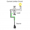
I'm using a current limiter circuit in which the bulb already fires up with a switch and outlet. So I can turn on the bulb when without the amp plugged in. I plugged my amp in by itself, there's no excessive hum, the power transformer doesn't hum loudly or heat up. The power tubes don't redplate. The voltages stabilize and don't drop or increase. I have the bias at -50volts
I dunno what you’ve built there, have you got a link to the design or plans it was based on?
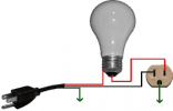
For it to limit current, all the mains current drawn by the amp passes through the light bulb filament.
I dunno what you’ve built there, have you got a link to the design or plans it was based on?
For it to limit current, all the mains current drawn by the amp passes through the light bulb filament.
It's all good, I'd have to find the page on Google images. My old limiter which I can't find it or the circuit diagram for was a limiter in which the bulb what only power up when the amp was fired up.
But the new one I built was deliberately wired to have the bulb fully powered up with the wall current.
My old limiter was built using this circuit.
What I'll do this weekend is reconfigure my new LBL to this circuit and test my amp again. Overall though it seems like it's operating correctly, but I do wanna make sure of that. Maybe the other LBL circuit I used is for testing something different.
I figured as much. I didn't really question it at the time when I built it, but I was curious on why the bulb was not responding that much with the amp. I'd see a slight dim in the illumination and back to being bright. I know an actual LBL is supposed to directly respond to the current draw of the amp. I apologize about the misunderstanding earlier. It caught me off guard for awhile

 sorry I meant the design of the light bulb limiter you’ve built.