Jtm45 2245 Reissue Mkii (1995 Model)

  • Thread starter deekayman
  • Start date
  • This site may earn a commission from merchant affiliate links like Ebay, Amazon, and others.

deekayman

New Member
Joined
Jan 18, 2009
Messages
12
Reaction score
0
Location
Australia
Hi

I recently bought JTM45 2245 MKII (1995 model) online and when I got it the sound was very sterile, nothing like my 1959 RI that I used to own.

It came with Valve Art KT66 power tubes and Tung Sol 12AX7 in V1 and 2 stock
Marshall 12AX7 tubes in V2 and V3.
Rectifier tube was replaced with diodes soldered across the V6 pins.
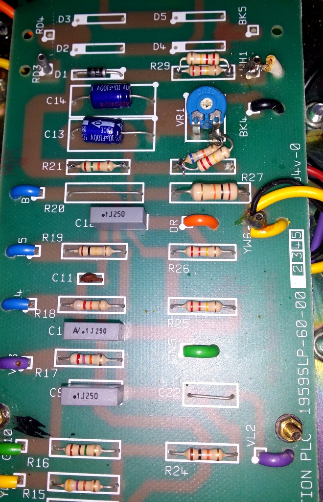
Screen resistor 1K/5W soldered across pins 4&6 on V4 & V5

I checked the bias and left side was 30mA and right side 27mA.
Plate voltage was 446VDC and 450VDC (pin 3 on V4 and V5).

I tried to increase bias by turning VR1(22K) and highest current I got with VR1 maxed out
was 35/31.5 mA.

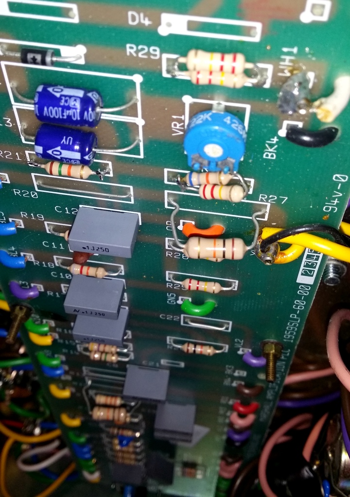
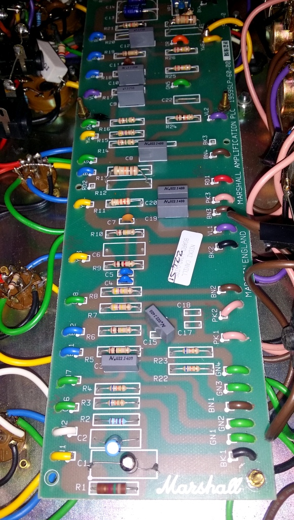
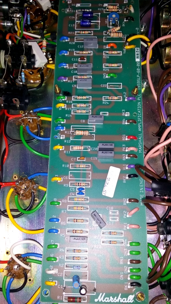
Someone before me has piggybacked/parallel wired two resistors in position R28 with
220K and 68K= 52K ; R29 with 2x220K=110K and also there are some components on the PCB
board that I can't find on any of schematics that I managed to download from the net.

I removed the piggybacked resistors from R29 and soldered the 180K resistor, value which I found in one of the schematics with KT66 in it.

Lowered the VR1 to its minimum and started it up.
Bias with VR1 at minimum on left side was 46.5mA(and increased to 50mA after 2 minutes)
and right side was 3mA less.
Plate voltage was 420VDC.

I shut it down coz I found it to be too high at lowest point of VR1.

What should I do to get the bias in the right bracket?

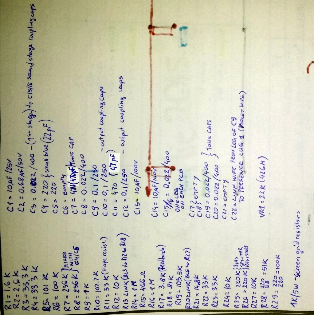
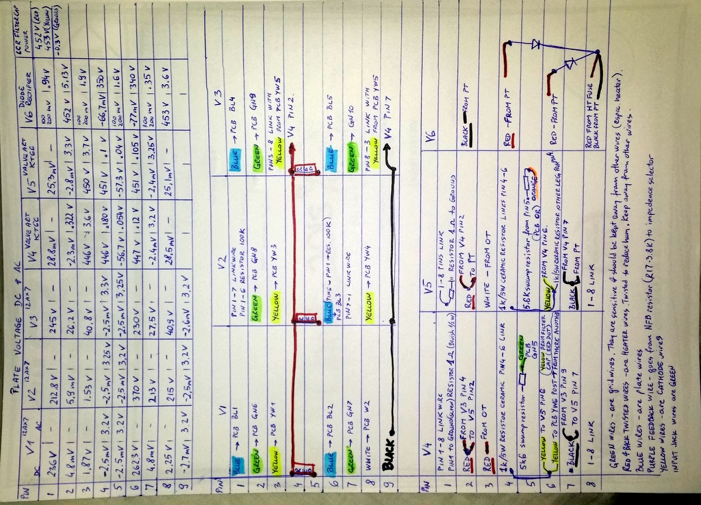
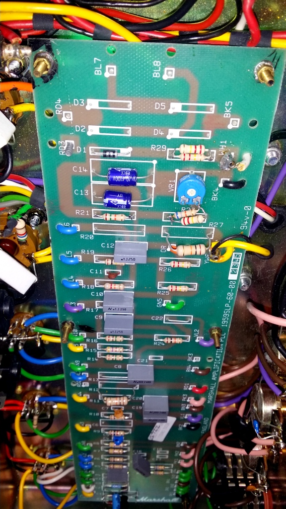
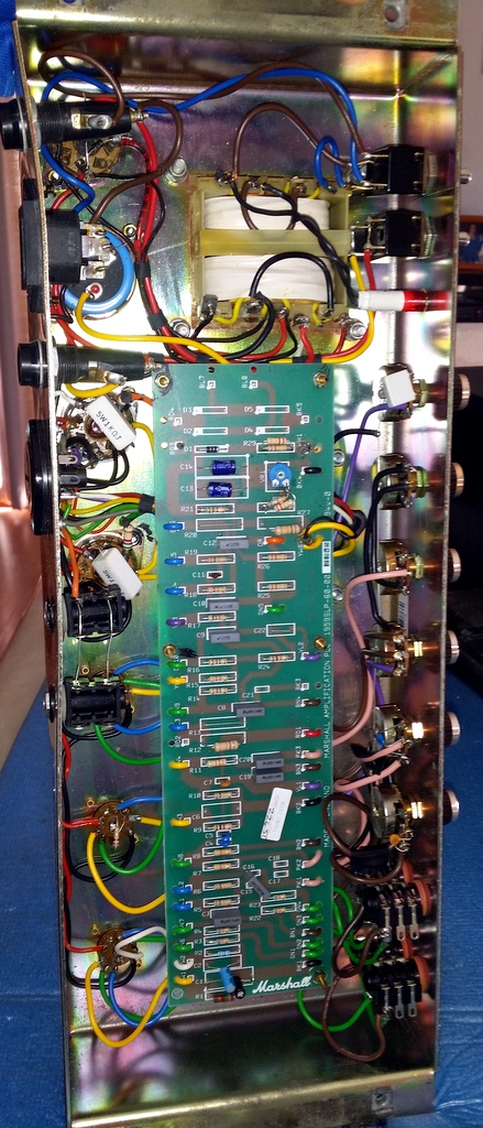
I have many photos of the PCB taken and voltages taken across all the pins plus all the resistor and capacitors numbers and values written down.

I would like if someone could have a look at them and tell me if there's any JTM45 RI schematic that is close to what I have inside or to point me to schematic which I should follow up to restore this amp to its best.

I'd like to experiment with return of rectifier tube and removal of the diodes from V6 which will drop the plate voltage down.
With that in place it would be another change with resistors around bias pot, I guess!?

For time being until everything is fixed let's work with diodes in place of rectifier just to get this thing going.

Your input would be much appreciated. Thanks
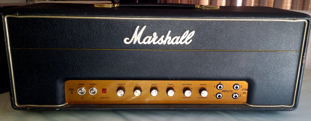
 

JCarno

Well-Known Member
Joined
Jun 30, 2010
Messages
1,403
Reaction score
585
Location
Finger Lakes
When I click on your links, this is what I get:
Marshall Amp Forum - Error
You do not have permission to view media within this album.
 

neikeel

Well-Known Member
Joined
Feb 12, 2014
Messages
8,457
Reaction score
9,622
Can't see your pics (forum denies permission).
R29 is the bias feed resistor (pre-diode) and with stock PT should be 220k, suggest you use it (180k is for an original Drake 1202-55PT).
R28 is the fixed resistor in series with your bias pot, stock is 68k. Anyone fiddled with R21.
Normally the plate voltage on stock one is under 400v and for correct bias I would expect around 45mA of bias current (how are you measuring it - 1 ohm resistors, bias probe or shunt? I prefer the stock 470R screen Rs with KT66s.
Usually I would vary R28 to get in range and leave R29 alone but YMMV!
Original:
jtm45-readable.jpg

Re-issue:
JTM45Reissue.gif
 

deekayman

New Member
Joined
Jan 18, 2009
Messages
12
Reaction score
0
Location
Australia
Access to photos should be fixed now, thanks for letting me know JCarno!

Thank you very much for your reply and for that reissue schematic neikeel!

Bias was adjusted by using the probe and DMM.

Now that I got the right schematic I'll compare it and trace my pcb with the components value, again.

I have already measured and wrote the values in one of the photos above, please have look at it (those values were measured with DMM when amp was
disconnected and discharged but I didn't desolder components from the board).

Looking at new reissue (bottom picture) schematic from neikeel, I see different values for:
-screen resistors (1K/5W instead 470K/5W)
- 4 x channel inputs resistors R3, R4, R22 & R24 (33K for mine instead 68k)
-R7 & R8 (236K instead 470K)
-R17 which goes to 16ohm tap (3.8K instead of 27K)
-R1 (1.6K instead of 820 ohm)
-C1 (10uF/25V instead of 330uF) and right next to it in C2 position I have 0.68uF which doesn't exist in schematic???


How much these "wrong" values and unknown C2 cap that are currently installed in the amp can play with the overall amp sound?


I'm concerned to install 220K in R29 coz I got the amp with that original 220K piggybacked with another 220K into R29 which
makes it 110K.
My bias was measured and result was 30/27mA but the VR1 couldn't give me more than 35mA when I maxed it out.
When I removed those resistors from R29 and soldered 180K resistor instead and with VR1 turned all the way left/minimum,
bias was 49/46mA which was high to start with.

If I install resistor of 220K into R29 I'm afraid that bias will be way too high with VR1 at its lowest!?
I guess something else then needs to change to compensate for that (you're suggesting to play with R28 resistor value instead?).


Normally the plate voltage on stock one is under 400v and for correct bias I would expect around 45mA of bias current...

Don't forget that plate voltage is higher due to diodes being in place of GZ34 rectifier tube.

[QUOTE ="neikeel, post: 1509576, member: 42534"]
I prefer the stock 470R screen Rs with KT66s.
[/QUOTE]

Could you please explain why is it so, thank you?
 

neikeel

Well-Known Member
Joined
Feb 12, 2014
Messages
8,457
Reaction score
9,622
Your amp has been converted to split cathode.
I would go stock with most values except C1 - keep it 10uF
 

deekayman

New Member
Joined
Jan 18, 2009
Messages
12
Reaction score
0
Location
Australia
Thank you neikeel again for your reply.

Could you please explain to me what is the reason, advantage/disadvantage of of split Cathode and what is
done to amp to achieve it? I don't understand that.

Amplifier used to belong to AC/DC's bass player Mark Evans and someone has done mods for him.


When you're saying "...go stock with most values..." what would it mean for the:
-C2 0.68uF which I have there and schematics don't show it

-Would you return screen resistors from 1K/5W to 470/5W?

I forgot to mention 2 x 5.6K swamp resistors from V4 & V5 pin5 to the PCB?
What happens to them?

Another thing is that pin 1 of V4 is linked to pin 8 with 1 ohm resistor and then to the ground (also V5 has the same link on those pins).
To keep or ...?
 

neikeel

Well-Known Member
Joined
Feb 12, 2014
Messages
8,457
Reaction score
9,622
Most of your board is stock (some resistors you were measuring not reading the codes I think?). The 68k input grids will measure 34k as in parallel).
I would go shared cathode V1 (remove the white wire - or just cut it 1cm off pin 8 and solder it to pin 3 to make it shared cathode. Fatter sound with a 45.
Those 1R resistors will screw with a bias probe - they are for biasing if you don't have a probe, you measure mV across resistor = bias current or so plus screen current ( which wil be 5mA to subtract) in mA. If you remove them (I would use then myself instead of probe) remember to use a piece of bus wire instead!
1k is usually for EL34s but you are ok with them. If you have a pair of 470R I would use them personally.
 

deekayman

New Member
Joined
Jan 18, 2009
Messages
12
Reaction score
0
Location
Australia
You're right about input resistors being measured by DMM instead of reading color codes on them...it makes sense now !

I understand now part about V1 being split cathode so I can try the reverse it back to shared cathode easily.

I have a set of 470R spare if needed.
Most important is that you helped me understand the reason why are those 2 resistor in the circuit.... to the take the bias reading across them.
Is that the only reason why are those two resistors in there?

If I remove them (which I'm not sure 100% about doing) are you saying to link pin 4 with pin 6 on V4 then do the same on V5?

Would you reinstall GZ34 instead of diodes?
What would that bring to the overall tone of the amp apart being saggy?
Would I lose a lot of clean headroom?


I have to admit that I tend to use some pedals for the dirty sound so this amp would be great
if I can get beautiful clean (think Little Wing) but somehow to get that with the strat or Les Paul guitar.
 

neikeel

Well-Known Member
Joined
Feb 12, 2014
Messages
8,457
Reaction score
9,622
I have a set of 470R spare if needed.
Most important is that you helped me understand the reason why are those 2 resistor in the circuit.... to the take the bias reading across them.
Is that the only reason why are those two resistors in there?

Yes - the 1R on pins 1&8 to ground are for bias only, a stock amp does not have them (many of us add them for easy biasing). The resistors on 4&6 are the screens (replace like for like, pin 4 is not used, 6 is the active one, the 4-6 wiring is used as a convenient place to mount the R, that is all, you could mount them flying direct to pin6 with the yellow screen feed wires in the breeze, but not recommended). You also have 5k6 on the grids.


Would you reinstall GZ34 instead of diodes?

Yes I would but it is not essential, the amp would only sag when dimed.


I have to admit that I tend to use some pedals for the dirty sound so this amp would be great
if I can get beautiful clean (think Little Wing) but somehow to get that with the strat or Les Paul guitar.

A well set up JTM45 will be perfect for that.
 

deekayman

New Member
Joined
Jan 18, 2009
Messages
12
Reaction score
0
Location
Australia
Well, here's the progress I've done.
Many thanks go to neikeel!:applause:who guided me in right direction.
Sound is finally back to what I expected from this amp and I'm using the jumper lead across 2 channels.


Amp was rewired back to shared cathode on V1.
R1 replaced with 820R but kept the value for C1 of 10uF as recommended.
R2 and C2 removed from the circuit.
C5 220pf removed.

Removed diodes from the V6 (rectifier) and put back JJ GZ34 in.
Bias resistor R29 replaced with stock value 220K .
R28 80K installed- played with values on that one until decent bias range was found across VR1.

Screen resistors replaced with 470R/5W (but still don't understand why/what is the difference from the previous resistor 1K/5W)?

Another thing I've done is to remove a cap 100pF wired across viper and ground on A1M (normal volume pot) coz schematic
doesn't show it but I kept the same value cap on A1M on Bright volume pot.
Was that cap added coz more bass was wanted on Normal channel or...???

Further things I'd like to do is:
-possibly install Lar Mar PPIMV - not sure
-replace 0.022 uF (x 5) and 0.1uF (x 3) from pcb with SOZO caps - do you think is it worth replacing?

I'm not sure why I'm hearing a hum through the speakers when Power switch is on, which stops as soon as I
flick the Standby switch off?


I have Tung Sol in V1 and stock Marshall tubes in V2 & V3.
What newer tubes (easy to find) would you go for and why?
 

ampmadscientist

Well-Known Member
Joined
Jun 26, 2014
Messages
17,849
Reaction score
12,230
Location
Bio-Isolation Lock Down
Screen resistors replaced with 470R/5W (but still don't understand why/what is the difference from the previous resistor 1K/5W)?

1k is EL34, 470 is 6L6 or 5881. The resistor limits the current when the amp is pushed hard.
If the wrong resistor is installed (like 470 for EL34) the fuse will blow.
So the resistor is determined by the type of output tube you are using.

Another thing I've done is to remove a cap 100pF wired across viper and ground on A1M (normal volume pot) coz schematic
doesn't show it but I kept the same value cap on A1M on Bright volume pot.
Was that cap added coz more bass was wanted on Normal channel or...???


No, it does not add any bass.
The bright cap was changed to make the channel have less upper mid range, and more highest treble frequencies.
Removing the cap just stops the brightness.
 

ampmadscientist

Well-Known Member
Joined
Jun 26, 2014
Messages
17,849
Reaction score
12,230
Location
Bio-Isolation Lock Down
"Amp was rewired back to shared cathode on V1.
R1 replaced with 820R but kept the value for C1 of 10uF as recommended.
R2 and C2 removed from the circuit."


Shared cathode is more non-stable than separated cathodes. Separated is better in a guitar amp, despite what people tell you.
Amps w/ shared cathode have way more problems.

Further things I'd like to do is:
-possibly install Lar Mar PPIMV - not sure


PPIMV: won't produce what you are expecting. What you really want to do is change the input to 2204 circuit....THEN add a master volume.
PPIMV by itself is going to be pretty useless.

-replace 0.022 uF (x 5) and 0.1uF (x 3) from pcb with SOZO caps - do you think is it worth replacing?

No. It's a complete waste of money, and a foolish idea. The circuit board is damaged very easily by inexperienced soldering.

"I'm not sure why I'm hearing a hum through the speakers when Power switch is on, which stops as soon as I
flick the Standby switch off?"

With no guitar plugged in, hum comes from 2 causes:
Power supply hum (like old filter capacitors)
Filament Hum (from the layout of the wiring) It's a buzzing noise.
But you should have a technician fix it.
 

neikeel

Well-Known Member
Joined
Feb 12, 2014
Messages
8,457
Reaction score
9,622
A JTM45 is a JTM45 and should sound like one. Not all Marshalls are the same and they do not have to be cascaded preamps to sound good.
If you want crunch at reasonable volumes you can try some low sensitivty speakers (eg Celection G12M20 which are 96dB) or, without wishing to be controversia,l a PPIMV used in moderation can help bring the volume down a little bit, but do not expect it to sound fantastic at less than 50% on the dial. You will be getting PI tube distortion rather than power tube distortion but it can be useful if you do not want to stretch to a good attenuator.
Replacing the caps is not the most cost effective way of getting the best tones from one of these, what you have done already is helpful but these simple circuits can benefit from good tubes (I like Mullards and Brimar and if you go for a PPIMV the best tube in the PI is a CV4004 or M8137 type), having said that I have a JTM45 on the bench at the moment with all Sovtek tubes (5881s, GZ34 and 12AX7) and it sounds amazing (it does have mustards and Pihers on the board but I am not sure that they can be the only reason).
Regarding the hum, there is an issue with the PT being 90 degrees off orientation. The PT and OT are very close and there is some issue with induction hum. You can also have heater wiring filament hum that can be improved a little with tight twists and ensuring it is pushed away tight to the chassis and all other preamp wires cross at right angles, good groundin scheme without loops can make big difference.
But it is what it is, so enjoy, and if not, decide why and then decide on why not and discuss solutins!
 
Top