Volodymyr
New Member
- Joined
- Aug 17, 2022
- Messages
- 17
- Reaction score
- 8
Hi folks,
I recently bought my first Marshall the JCM 2000 DSL 50.
I have spent a few days, playing around with it, switching between channels and mods, trying to pool all possible sounds from it.
Some moment, when I was playing on a red channel Lead 1, the gain suddenly disappeared, the volume dropped a bit and the sound became thin and lifeless, all lows went as well, sounds like a wah-wah.
At the same time, the green channel is still functioning as should, from a clean to punchy JCM 800-like tone.
Cleaning up the tubes and sockets, and trying new tubes - didn't help at all.
I also didn't find any blown, burned, or unsoldered components inside the amp, it looks new.
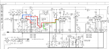
I'm not good at schematic reading but I was able to find the signal paths for both channels the red channel uses additional, V1b, gain stage, and the green one skips it
I highlighted it on a schematic
I have tested the relay that switches channels, and it works as expected, the signal switching from CON6 to CON4 (at least the multimeter shows some AC voltage at corresponding pins)
The optocoupler changes its resistance as well
My last idea is to check the tone stack, but what to look for?
So I'm out of ideas, does anyone have an idea where the issue maybe?
I recently bought my first Marshall the JCM 2000 DSL 50.
I have spent a few days, playing around with it, switching between channels and mods, trying to pool all possible sounds from it.
Some moment, when I was playing on a red channel Lead 1, the gain suddenly disappeared, the volume dropped a bit and the sound became thin and lifeless, all lows went as well, sounds like a wah-wah.
At the same time, the green channel is still functioning as should, from a clean to punchy JCM 800-like tone.
Cleaning up the tubes and sockets, and trying new tubes - didn't help at all.
I also didn't find any blown, burned, or unsoldered components inside the amp, it looks new.
I'm not good at schematic reading but I was able to find the signal paths for both channels the red channel uses additional, V1b, gain stage, and the green one skips it
I highlighted it on a schematic
I have tested the relay that switches channels, and it works as expected, the signal switching from CON6 to CON4 (at least the multimeter shows some AC voltage at corresponding pins)
The optocoupler changes its resistance as well
My last idea is to check the tone stack, but what to look for?
So I'm out of ideas, does anyone have an idea where the issue maybe?