Hi all!
I sold my original JVM410HJS about 7 years ago, and have regretted it ever since; and as of yesterday, I'm now the proud (re)owner of one; they're bloody hard to track down!

I wasn't going to mod it, but I just couldn't help myself.... so today I spent a few hours applying the negative feedback mod and the Rhoads / AFD mods. Only trouble is, the original forum with the guide shut down.... and the only post I could find was this a couple on here using photos of my original mods from thefretboard forum. Thankfully I had the original photos on my phone, and could figure out the wiring etc. Easily the most stressful part was soldering across that resistor on the board; a little bit of poo came out, especially as I melted the cap next to it a bit!
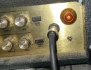
Check out the negative feedback dial and the Rhoads / AFD switch on the right:

Anyway, here are the mods for anyone else interested. Obviously, do this at your own risk:
Negative Feedback Mod
Instead of placing another resistor in parallel with R58, I cut the 3rd blue cable at the NFB block - the 3 blue leads on the board, and the cable to cut handily has an arrow above it on the PCB - and put a 1Meg log pot between the cables. You'll need to obviously extend the cables by soldering extra lengths to them.
This has the result of allowing you to change the negative feedback; fully left (or '0') is stock NFB - which I actually prefer - and moving clockwise gradually increases the resistance for the NFB. This has the effect of 'opening the amp up'; you'll notice the depth and presence don't have much impact (if any) when the new NFB pot is fully clockwise.


AFD / Rhoads Mod
This was the scariest mod to do due to having to solder to an existing resistor on the PCB, and it's a VERY tight fit.
To do this, get an On-On-On switch. For the middle two arms, wire a length of cable to each side. For the top two, connect a 3k7 resistor (I had to use a 2k7 and a 1k in series). For the bottom, connect a 100nf / 0.1uf cap in series with a 2k7 resistor.
Now for the shit-your-pants bit.....
Find resistor R161 on the PCB; it should be around the 2nd power tube socket on the left of the board. You need to solder one of the ends of lead you connected to the middle connections on the switch to one side, and the other cable to the other side. You probably want to discharge the filter caps before doing this! I didn't but I'm stupid.
The point of this mod is that when you have the switch in the middle, it is the stock JVM410HJS gain stages. Flip the switch up, and you get the AFD mode; seems to have more mids and bit more girth and gain. Flip it down, and you get the Rhoads mod - pure filth. More gain, more body and more sizzle.


Hope that helps anyone else looking to do these - I'll try and record some vids soon.

Don't ask me 'how' they work, as I have no idea.....!
I sold my original JVM410HJS about 7 years ago, and have regretted it ever since; and as of yesterday, I'm now the proud (re)owner of one; they're bloody hard to track down!
I wasn't going to mod it, but I just couldn't help myself.... so today I spent a few hours applying the negative feedback mod and the Rhoads / AFD mods. Only trouble is, the original forum with the guide shut down.... and the only post I could find was this a couple on here using photos of my original mods from thefretboard forum. Thankfully I had the original photos on my phone, and could figure out the wiring etc. Easily the most stressful part was soldering across that resistor on the board; a little bit of poo came out, especially as I melted the cap next to it a bit!
Check out the negative feedback dial and the Rhoads / AFD switch on the right:
Anyway, here are the mods for anyone else interested. Obviously, do this at your own risk:
Negative Feedback Mod
Instead of placing another resistor in parallel with R58, I cut the 3rd blue cable at the NFB block - the 3 blue leads on the board, and the cable to cut handily has an arrow above it on the PCB - and put a 1Meg log pot between the cables. You'll need to obviously extend the cables by soldering extra lengths to them.
This has the result of allowing you to change the negative feedback; fully left (or '0') is stock NFB - which I actually prefer - and moving clockwise gradually increases the resistance for the NFB. This has the effect of 'opening the amp up'; you'll notice the depth and presence don't have much impact (if any) when the new NFB pot is fully clockwise.
AFD / Rhoads Mod
This was the scariest mod to do due to having to solder to an existing resistor on the PCB, and it's a VERY tight fit.
To do this, get an On-On-On switch. For the middle two arms, wire a length of cable to each side. For the top two, connect a 3k7 resistor (I had to use a 2k7 and a 1k in series). For the bottom, connect a 100nf / 0.1uf cap in series with a 2k7 resistor.
Now for the shit-your-pants bit.....
Find resistor R161 on the PCB; it should be around the 2nd power tube socket on the left of the board. You need to solder one of the ends of lead you connected to the middle connections on the switch to one side, and the other cable to the other side. You probably want to discharge the filter caps before doing this! I didn't but I'm stupid.
The point of this mod is that when you have the switch in the middle, it is the stock JVM410HJS gain stages. Flip the switch up, and you get the AFD mode; seems to have more mids and bit more girth and gain. Flip it down, and you get the Rhoads mod - pure filth. More gain, more body and more sizzle.
Hope that helps anyone else looking to do these - I'll try and record some vids soon.
Don't ask me 'how' they work, as I have no idea.....!