Mojotone JTM45 Kit Refresh - Suggestions for Improvements While I'm At It?

  • Thread starter ThreeChordWonder
  • Start date
  • This site may earn a commission from merchant affiliate links like Ebay, Amazon, and others.

ThreeChordWonder

Well-Known Member
Joined
Jan 31, 2021
Messages
485
Reaction score
564
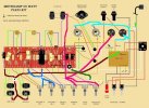
Coming along quite nicely, although I'm one capacitor short of a circuit board [thats a new way of putting it, right?].

As I've said before, I've upped the specified 1/2-watt resistors to 1-watt, 1-watt yo 2-watt, etc., so there's a big 1K 10W on the left.

Some components are only tack-soldered right now, as I have wires to fit in the holes.

The white wires will go to my off-board tube bias pot.

I will be tapping at the 100 nF / 220k junctions, for my PPIMV. That will be a dual 250k pot with 2.2M bleed resistors. Normally those junctions go by wires to 5.1K resistors attached to pins 5 (control grids) on the EL34 power tube sockets. I'm just interrupting the connections with a dual pot and bleed resistors.

The ground bus is in, on top the board. 18 awg single core. I'm not sure whether bare wire on top is a good idea though. Thoughts anyone? I can re-do it on the bottom and use insulated wire if that's required.

20240820_200825.jpg
 

ThreeChordWonder

Well-Known Member
Joined
Jan 31, 2021
Messages
485
Reaction score
564
Getting closer.

I'm still waiting for three pots to arrive, one for the treble, one for the presence, and a replacement dual 250k with hopefully better balanced individual pots. I'm also waiting for some silver mica caps.

But I decided to go ahead and start, nearly finish, installing the circuit board.

All the tube sockets are connected, as are the input jacks and the pots that I do have.

The Grey wires are shielded wires for the PPIMV taps off the board. They cross right over the board, so they need shielding (apparently).
I also moved the ground bus to the underside of the board, and used a continuous single length of 18 gauge insulated solid core. Where I needed to connect the wire to a turret, I stripped off the insulation, made little U shapes pinched up tight enough to fit and stuffed them in the holes for soldering.

I think it's starting to look good.210948.jpg
 

Joesatch

Active Member
Joined
Mar 30, 2012
Messages
155
Reaction score
151
I use Larry grounding. Also you can easily mod the JTM45 into a dirty shirley which i have done. Make it switchable to get JTM45 tones or 800 tones.
 

Attachments

  • larry.jpg
    larry.jpg
    82.4 KB · Views: 15

ThreeChordWonder

Well-Known Member
Joined
Jan 31, 2021
Messages
485
Reaction score
564
I use Larry grounding. Also you can easily mod the JTM45 into a dirty shirley which i have done. Make it switchable to get JTM45 tones or 800 tones.
Thanks for that.

The grounding is already complete, sketch to follow when I'm near a PC.

I'll have to sit down and compare JTM45 and 800 wiring diagrams, but TBH I'm happy enough with the JTM45 for now.
 

ThreeChordWonder

Well-Known Member
Joined
Jan 31, 2021
Messages
485
Reaction score
564
Here's the grounding scheme I came up with. The new grounds are shown in red.

Mototone JTM45 Kit with TCWs Ground Bus Scheme.png

The ground bus wire across the back of the pots has been deleted, as have the individual links to it from the pots and the turret board.

A new ground bus, 18 AWG insulated copper single core, has been added along the bottom of the turret board. It's one length of wire, starting with the "Middle" tone pot ground, with an extension out to the 100 NF capacitor tail on the "Presence" pot ground. It connects to all the grounds required by the turret board. I stripped the insulation off and made little loops which I stuffed into, then soldered into, the holes in the bottoms of the appropriate turrets. It then goes out to a new grounding point, a #6 machine screw fitted through the chassis by the input jacks. A keep nut holds everything down tight.

The input jacks and input Volume pots have their own grounds, also shown in red. I could, however, extend the ground bus to include them, as shown in blue. The revised ground bus would come off the end of the 250 nF electrolytic capacitor on the right end of the turret board, go out to the Bright volume pot ground, then over to the Normal volume pot ground, then to the input jacks, then back to the grounding screw. I wouldn't create any "loops" in the Ground Bus. Thoughts on that welcomed, please.
The Power Transformer grounds, plus the two 32/32 uF smoothing capacitors (the big can capacitors) are all grounded using one of the Power Transformer mounting bolts and a big keep nut.

The chassis to mains ground is separate and uses a different Power Transformer mounting bolt and a keep nut. Anyone who says chassis grounds have to be soldered should look at my washing machine (which I'm currently replacing the door seal on).

The EL34 grounds are local using their socket mounting screws and keep nuts. I've put 1-ohm resistors into the grounds, and I've added probe wires and probes on the back of the chassis so I can bias the power tubes without having to probe the guts of the amp. Much safer.

I've also added a separate fuse in the yellow wire between the Rectifier tube and the 32/32 uF can capacitor mounted to the side wall. That capacitor feeds the standby switch and then from there wires go out to the Choke and the Output Transformer. I don't like relying on the center tap HT fuse, but I've kept it as I've been told it protects the Power Transformer.

Other than that, the only real mods are the PPIMV and the off-board bias pot.

The PPIMV wires interrupt the link between the 100 nF capacitor / 220 kOhm resistors and the 5.1 kOhm grid resistors. The pot is a dual 250k / 250k, with 2.2 MOhm bleed resistors. The ground connections on the pots are separately grounded also. By the way, I checked with Mojotone and they seem okay (or at least didn't tell me "don't!") with using 4.7 kOhm 2-watt resistors in place of the 5.1 kOhm 1/2-watt units, which I can't find in 2-watt versions. The original resistors are +/- 10%, so minimum 4.59 kOhm. The replacements are +/-1 1%, so minimum 4.65 kOhm. The intent here is that the 2-Watt versions are mechanically sturdier that the 1/2-Watt versions.

The off-board bias pot is a simple 50k pot, wired as a variable resistor, not as a potential divider. It worked fine before this round of mods.
 

ThreeChordWonder

Well-Known Member
Joined
Jan 31, 2021
Messages
485
Reaction score
564
I've moved all the grounds off the PT bolts now.

The ground scheme is curretly as follows:

1. The mains ground goes to one #8 bolt and keep nut, near to, but separate from, the PT mounting bolts. This wire should be long enough that in the highly unlikely event that the mains plug sticks in the mains socket and both get pulled out, the live or hot should separate first. 1/4 inch spade connectors BTW.

2. The PT HT and LT (heater circuit) enter taps and the two 32 /32 uF can capacitors share a second grounding bolt, again separate from, but near to, the PT mounting bolts.

3. There's a ground bus along the turret board which starts at the presence pot grounding capacitor, then the the middle tone pot, them along the turret board grounds, ending in a third grounding point near the input jacks. It can be extended, if thought worthwhile, to include the input volume pots and input jacks.

4. The input volume pots currently have individual grounds, using the same grounding bolt through the chassis described above.

5. The input jacks share one separate (but common for all four jacks) ground connection to the grounding bolt through the chassis described above.

6. The EL34 tube sockets are individually grounded on their respective mounting bolts. It would need long pieces of wire to reach the input area grounding bolt.

7. The PPIMV dual pots are separately grounded near the dual pot.[/list]

I could extend the ground bus (item 3 above) to loop in the volume pots and / or the input jacks. Thoughts on this welcomed.

Finally, a quick question. Would moving the cap on the presence pot from the ground side to the input side remove the noise I'm getting when I turn the pot?
 

ThreeChordWonder

Well-Known Member
Joined
Jan 31, 2021
Messages
485
Reaction score
564
I'm getting low voltages across the board, maybe all 10% down on what's shown on the wiring diagram. I don't think that'll be a problem, generally, but I'm wondering if the voltages quoted are optimistic or require a higher power PT than the one provided (Mojotone 7020300). Is there anything I should check?

Another problem I'm having is the the power tube, EL34, bias currents are running away, up to 100mA, maybe more, before the master fuse blows.

I suspect a dodgy tune socket, and I'm going to go ahead and replace both, but is there anything else I should check?

Instead of checking tubes in, I can check the tubes out (and later tubes in) voltages at pins #3, right? What range should I be seeing?

One final point. The resistors to the EL34 pins #4 (screw grids) are shown as 470 ohm 1W ceramics or cement resistors (bigvgray ones anyway). They're both fed in parallel off a 1 kohm 5W ceramic / cement one on the turret board. I'm going to up them to 2 or even 5-watts anyway. The question is that I've seen some diagrams with 1 kohms instead of the 470s. Is there a reason and / or advantage in this?
 

2L man

Well-Known Member
Joined
Sep 30, 2020
Messages
401
Reaction score
282
Higher power tube current make HV lower! Take power tubes out and measure that all negative control grid voltages are the same and their adjust ranges come the same. Then leave adjust highest negative.

Measure also all anode and screen socket voltages.
 

2L man

Well-Known Member
Joined
Sep 30, 2020
Messages
401
Reaction score
282
Measuring that CG voltages in sockets #5 are the same mean that Coupling Capacitors do not leak current from PI anode HV. Leaky capacitor increase anode/cathode current because it change bias. When PI tube is removed elevate other end if CC to HV and possisble leaky CC reveal symptom better.

When Screens have individual resistors without filter capacitor screen voltage drop fast if/when screen current increase. This is safety mechanism for Screens. This also has some effect to sound/distortion because screen voltage drop then drop the anode current.

Screen current increase if/when playing has majority of frequencys inside loudspeaker resonance peak and then anode voltage swing tips can go very low to less than 100VDC. Mechanism there come when loadline angle turn shallow.

1k is "typical" for EL34 but I have seen also 1.2k and 1.5k which possibly are needed when high voltage is very high.

I have understood metal/dropD guitarists prefer speakers which resonance frequency is lower? :)
 
Last edited:

PelliX

Well-Known Member
Joined
Jun 16, 2020
Messages
7,154
Reaction score
14,570
Just a generic pointer; that 10W resistor is likely to get fairly warm - space it if possible from the cap next to it. Same applies for the 16uF cap and high power resistor in the middle of the board.

Love the bias pot, haha!

Also, are you installing protection diodes on the rectifier?

The standby switch resistor is not a bad idea, but I'd probably still avoid stressing it by swapping cabs around with it switched on. It might be fine, one would have to do the maths - I prefer to err on the side of safety there.
 
Last edited:

ThreeChordWonder

Well-Known Member
Joined
Jan 31, 2021
Messages
485
Reaction score
564
Thanks for that.

The big resistors are spaced quite a bit off the board already.

The 16 uF (I'm presuming a typo by you) also has plenty of air around it.

I'm not doing resistors on the standby switch, and it's a tube rectifier (GZ34), so no diodes. Out of interest, though, what sinoze caps would you use on a 100-watt plexi diode rectifier? Likewise on my Hiwatt DR103 copy? I presume ceramic disc or lozenge shaped one would do here, 500 or higher volts, of course.

Anyway.

I decided to fit all new tube sockets. Then I ran the thing up on the Variac, biased the tubes to 35 mA, then plugged it in to the cab and cabinet. The noise  seems to have gone, but im not getting much actual output at all, so I'm not really sure.

Measured voltages seem down by 20% across the board - 311 VAC off the PT where I should be seeing 350, and 385 VDC after the rectifier where I should be seeing 465-470. All the other voltages are down too.

I've already tried a new rectifier tube without any change, and next up I'm going to swap out the EL34s. I have a spare matched pair of JJs on hand.

Anything else I can look for would be appreciated. I've got 1k 5W, instead of 470 5W, resistors on the screen grids BTW. I have 470s on hand if needed.
 

PelliX

Well-Known Member
Joined
Jun 16, 2020
Messages
7,154
Reaction score
14,570
The 16 uF (I'm presuming a typo by you) also has plenty of air around it.

Yes, dammit, haha! Cool, it looked pretty tight on the pics.

I'm not doing resistors on the standby switch, and it's a tube rectifier (GZ34), so no diodes.

Particularly in the case of a valve rectifier you want protection diodes.

See this: https://robrobinette.com/Generic_Tube_Amp_Mods.htm#Protection_Mods

Won't hurt, might save your day. By the looks of it, they've rearranged the standby switch to avoid the hot switching, so that should be fine.

Then I ran the thing up on the Variac, biased the tubes to 35 mA, then plugged it in to the cab and cabinet. The noise  seems to have gone, but im not getting much actual output at all, so I'm not really sure.

You need the full voltage to properly bias it, so I assume you had the variac dialed to wall voltage?

Measured voltages seem down by 20% across the board - 311 VAC off the PT where I should be seeing 350, and 385 VDC after the rectifier where I should be seeing 465-470. All the other voltages are down too.

What's your wall voltage and how does this compare to the PT's primary winding that you're using? How about the heater voltage, is that down, too?
 

2L man

Well-Known Member
Joined
Sep 30, 2020
Messages
401
Reaction score
282
PT datasheet show it has two 120V primary coils. Verify that you have their phases connect correct! Coil ends which are pictured close each other must be connect together and mains is feed to the other ends for 240VAC mains.
 

2L man

Well-Known Member
Joined
Sep 30, 2020
Messages
401
Reaction score
282
Looking at this drawing, am I to understand that the neutral is fused and not the live? Surely it should be the other way around?
CT circuit fuse burn and stop HV current flow when there come one over current failure and amp stop working. However better protection would come when each rectifier anode circuits have fuses. Now if rectifier diode get a short its fuse burn. Then at least in theory amp can keep producucing low power sound when current flow thru other diode but if higher power is tried to take also its fuse will burn.

Depending of the transformer unsymmetric secondary current flow saturate the core which then tend to increase primary current flow and then primary fuse might burn first. This is how Toroidal PT seem to behave.
 
Last edited:

ThreeChordWonder

Well-Known Member
Joined
Jan 31, 2021
Messages
485
Reaction score
564
I'm not fitting capacitors to the tube rectifier in the JTM45 because (1) I don't know what values to use (2) I'm not sure how to connect them (3) there's not much room down there and (3) bigger fish to fry right now.

Bias was set with the amp plugged directly into the mains.

The mains voltage here is 120 VAC here. I checked it at the mains socket. It's fine.

The PT is wired correctly.

On the input side blue/ black and all black go to the hot pole, yellow/black and white/ black go to the neutral pole.

On the output side, the reds go to pins 4 and 6 and there's a yellow off pin 6 that goes to the 220k / 4007 diode on the far left end if the board. That provides the -60 VDC for biasing the EL34s. The yellow/red center tap goes to a fuse then to ground.

The fuses are good.

Two yellows come off pins 2 and 8, 8 has a 47 nF cap to ground. The gray off pin 2 goes to the 32/32 uF can capacitors on the side wall then to the standby switch, the to the OT and choke.

The EL34s bias was checked with the amp plugged directly into the mains.
 
Last edited:

ThreeChordWonder

Well-Known Member
Joined
Jan 31, 2021
Messages
485
Reaction score
564
Here's a voltage survey.

The numbers in green show what the Mojotone wiring diagram says the voltages should be.

The numbers in read show the readings I got with a digital multimeter.

I.ve tried swapping out the GZ34 for a brand new one, it didn't make any difference, so the old one has gone back in. Same deal with the EL34s.

Next up I can try changing the ECC83s, see if I have a duff preamp tube.


Voltage Readings 0SEP24 10-00 am.png
 

PelliX

Well-Known Member
Joined
Jun 16, 2020
Messages
7,154
Reaction score
14,570
I'm not fitting capacitors to the tube rectifier in the JTM45 because (1) I don't know what values to use (2) I'm not sure how to connect them (3) there's not much room down there and (3) bigger fish to fry right now.

I guess you mean diodes and the page suggests 1N4007's. Beefier is fine, but let's not overcomplicate things. There are ultra-fast avalanche type diodes, but the 1N4007's (which are common and dirtcheap) would be a good place to start. Your call, of course. Agree on the room, I did this in my JTM45 which is a little less crowded than your chassis by the looks of it and had to remove the fuse holder to get good access there.

The numbers in green show what the Mojotone wiring diagram says the voltages should be.

You missed the heaters. The heaters should, loaded, be at 6.3VAC. No discussion on that one. The reason I stress this is because A) lower heater voltage is not too good for the valves (not instant death either, though to be honest) and B) it's a solid reference point. If the heaters are off by the same factor as your HT, there's likely a mismatch somewhere. If your HT is being bogged down, the heaters would still be correct as they use a completely different secondary winding on the PT.
 

Latest posts


Top