Need Help With 5E3 FX Loop Install

paul-e-mann

Well-Known Member
Joined
Dec 7, 2009
Messages
21,893
Reaction score
25,427
Location
USA
I installed a loop from the Rob Robinette page in my amp and it doesnt work as expected. Here's the mod.

4n3mcjx.png


The difference in his plan and my amp is his bright channel is on the right and mine is on the left, so I went as planned and turned my normal channel into an fx loop. The problem is I get no sound out of my bright channel jacks now but if I plug guitar into normal channel jacks I get sound. Also neither volume works or the tone works. I do have a master volume installed and that works. Also my volume is nowhere near as loud as it used to be. Here is the layout I used to build my amp.

J1BEKdZ.jpeg


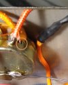
Here is the completed mod in my amp, left jacks is bright channel, right jacks is fx loop.

EM3KiYi.jpeg
 

Creach

Member
Joined
May 20, 2023
Messages
65
Reaction score
55
Hello paul-e-mann,

Is this wire connected? Not easy to see clearly.
 

Attachments

  • Screenshot_20240918_080653.jpg
    Screenshot_20240918_080653.jpg
    637.1 KB · Views: 6

paul-e-mann

Well-Known Member
Joined
Dec 7, 2009
Messages
21,893
Reaction score
25,427
Location
USA
I just noticed something, basically I disconnected the normal jacks from the stock circuit, they used to be connected to the V1A grid stopper, notice now the pair of 68K resistors that used to be connected to the normal 2 jack are now not connected to anything. Is this a problem, possibly causing an open circuit? Do the pair of 68K resistors need to be terminated together to close the circuit? Or just be disconnected from V1 pin 2?

Another thing I noticed, look at the right edge of the mod drawing, it looks like the normal jacks may possibly still be connected I see a little bit of the 68K resistors, maybe I wasnt supposed to remove the normal jacks at all and was supposed to add an additional pair of jacks for the loop? I just assumed the loop jacks were the normal jacks cuz the plan included rewiring the normal volume pot.

I dont use the normal channel any way, I wouldnt mind removing it all together and use the jacks and volume pot for a loop as showed in the mod. Maybe I just gotta get some instruction on how to remove the normal channel all together to close the circuit.
 
Last edited:

2L man

Well-Known Member
Joined
Sep 30, 2020
Messages
402
Reaction score
282
I just noticed something, basically I disconnected the normal jacks from the stock circuit, they used to be connected to the V1A grid stopper, notice now the pair of 68K resistors that used to be connected to the normal 2 jack are now not connected to anything. Is this a problem, possibly causing an open circuit? Do the pair of 68K resistors need to be terminated together to close the circuit? Or just be disconnected from V1 pin 2?

Another thing I noticed, look at the right edge of the mod drawing, it looks like the normal jacks may possibly still be connected I see a little bit of the 68K resistors, maybe I wasnt supposed to remove the normal jacks at all and was supposed to add an additional pair of jacks for the loop? I just assumed the loop jacks were the normal jacks cuz the plan included rewiring the normal volume pot.

I dont use the normal channel any way, I wouldnt mind removing it all together and use the jacks and volume pot for a loop as showed in the mod. Maybe I just gotta get some instruction on how to remove the normal channel all together to close the circuit.
Refer the schematic which are plenty in internet. 68k grid block resistors are seried between input jacks and control grids so without connection the circuit does not function!

Draw a short line to each component leg in schematic where they meet a "Connection Point". Wire is a two leg component so there come several new CPs to schematic! Then when all legs are "ticked" in that CP and you find solder good looking it and measuring zero ohm resistance between two separate legs draw a circle over that junction and proceed to next.
 
Last edited:

Pete Farrington

Well-Known Member
Joined
Jan 18, 2021
Messages
3,220
Reaction score
4,249
Location
Staffordshire UK
I installed a loop from the Rob Robinette page in my amp and it doesnt work as expected. Here's the mod.
it looks like the normal jacks may possibly still be connected I see a little bit of the 68K resistors, maybe I wasnt supposed to remove the normal jacks at all and was supposed to add an additional pair of jacks for the loop? I just assumed the loop jacks were the normal jacks cuz the plan included rewiring the normal volume pot.

I agree, the page has insufficient detail for me to understand how it's supposed to work, what the intended functionality is supposed to be.


paul-e-mann

Well-Known Member
Joined
Dec 7, 2009
Messages
21,893
Reaction score
25,427
Location
USA
Refer the schematic which are plenty in internet. 68k grid block resistors are seried between input jacks and control grids so without connection the circuit does not function!

Draw a short line to each component leg in schematic where they meet a "Connection Point". Wire is a two leg component so there come several new CPs to schematic! Then when all legs are "ticked" in that CP and you find solder good looking it and measuring zero ohm resistance between two separate legs draw a circle over that junction and proceed to next.
I'm not sure what you're telling me, can you rephrase, thanks.

After digging around a little bit I think I gotta at least have a jack connected to each channel to complete the circuit, I'm looking into juggling the jacks so the high jacks of each channel are connected and the low jacks will be the effects loop. Thoughts?

Although I wouldnt mind just having the jacks for the bright channel only and get rid of the normal channel, but I havent found any mods to show me how to do this.

The part I dont understand about the effects loop mod is it uses the normal volume pot for loop level, but now you have no volume for the normal channel?
 
Last edited:

paul-e-mann

Well-Known Member
Joined
Dec 7, 2009
Messages
21,893
Reaction score
25,427
Location
USA
So I spoke to Rob Robinette and he said the loop jacks are in addition to the current 4 bright and normal jacks the amp already has. I dont have a use for 4 inputs so I found a mod on his site to go from 4 inputs to 2 inputs, so I performed this mod. Now I have the 2 low inputs available for the loop. So I did both of these mods and it still insnt working right so I'm stuck again. Right now I get sound if I plug guitar into either of the loop jacks and nothing in the other jacks. Here's the 2 jack conversion mod for reference:

BclNwkw.png


Here is how my amp looks now, the 2 bottom jacks are bright and normal high jacks, and the 2 top jacks are the eliminated bright and normal low jacks now used for effects loop. So I'm still stuck if anyone has any ideas.

O90iPSj.jpeg


How it looks on the top

qLGQEuc.jpeg
 
Last edited:
Top