No Presence on TSL602

  • Thread starter Rockraver
  • Start date
  • This site may earn a commission from merchant affiliate links like Ebay, Amazon, and others.

Rockraver

Member
Joined
May 6, 2009
Messages
191
Reaction score
21
Location
Ringwood, NJ
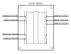
Hey fellas, I recently re-installed my original Dagnall TXOP-00002 OT in my TSL602 (after trying out a Mercury Magnetics OT), and a weird thing is now happening. I have definitely lost some volume and, my Presence Pot and Deep Switch no longer seem to function.

I did a DC analysis and everything checks out except for the EL34 plates and screen grid voltages. There is 0VDC on V6's Plate yet, there is 468VDC on V5's Plate. There should be 468VDC on both plates, correct? Also, there is 457VDC on V5's Screen Grid and 446VDC on V6's Screen Grid. That's an 11V difference and, if i'm not mistaken, they should both be roughly the same. Just like the plates should both be the same. I'm assuming that the Screen Grid discrepancy is due to the Plate discrepancies. ?

When I check the OT Primaries, one of the primaries has 468VDC (the one being fed by V5's Plate) but, the other primary has 0VDC, meaning that, there isn't any voltage coming from V6's plate. Thinking that maybe my problem might be the PI, I checked them voltages as well and, I found that one plate was putting out 278VDC while the other one put out 284VDC so, I don't think there's any problem with the PI.

When I ran an AC analysis using my scope and a 1V p-p 400Hz signal, I seen the same anomalies and, they matched my DC analysis. In other words, the AC signal on V5's plate is at least 8 times larger than that found at V6's plate. Also, the signal at the Negative Feedback tap off the OT was quite weak (only about 12V p-p which, if i'm not mistaken, is way too low to drive the Presence and Deep Switch circuitry). Either way, there is no audibly discernable effect when I turn the Presence Pot or engage the Deep Switch.

Now, if i'm not mistaken, an OT is a go, no go type device. That is, when it dies, it dies. End of story. So, what could be the cause of my problem? The tubes in there were working fine before but, i'll admit I haven't swapped the EL34's. I guess i'm afraid of blowing another tube if, that indeed is what's happening here.

Any thoughts?
 

Rockraver

Member
Joined
May 6, 2009
Messages
191
Reaction score
21
Location
Ringwood, NJ
Feedback wire is in place. It's one wire going from a pin on the OT to the board. Also, I swapped V5 and V6, hoping the problem would follow the tube but, there was no difference. I checked the voltages of all the compnents around the PI and PA section but, i've yet to find a bad component.

I'm wondering if a trace under the board has gone south. I don't know. It seems like i'm getting a good amount of bias drift as well. I've had to adjust it a few times.

Anyway, it's now quite late and I already gave up for the night so, i'll try again tomorrrow. I also sent Marshall support an email so, maybe they have some ideas.
 

Jonathan Wilder

Well-Known Member
Joined
Oct 12, 2009
Messages
6,163
Reaction score
747
Location
Greenville, SC
Feedback wire is in place. It's one wire going from a pin on the OT to the board. Also, I swapped V5 and V6, hoping the problem would follow the tube but, there was no difference. I checked the voltages of all the compnents around the PI and PA section but, i've yet to find a bad component.

I'm wondering if a trace under the board has gone south. I don't know. It seems like i'm getting a good amount of bias drift as well. I've had to adjust it a few times.

Anyway, it's now quite late and I already gave up for the night so, i'll try again tomorrrow. I also sent Marshall support an email so, maybe they have some ideas.

Hmm...I think you misunderstood me...Don't worry I'll repeat...

Did you forget to reconnect your negative feedback wire? Are you 100% positive that your negative feedback circuit is in tact?
 

jaek

New Member
Joined
Sep 21, 2009
Messages
177
Reaction score
7
on my DSL the OT partially fried. The amp still made noise just cut in and out alot with less volume in the 7-10 range on the volume knob. Replaced the OT (with a little help from MarshallForum) same tubes and bias and the problem was solved.
 

wpb

Member
Joined
Jan 4, 2011
Messages
163
Reaction score
7
Are you sure you wired the OT correctly? If you have 468V on one primary and 0V on the other, the OT is bad.

Pat Burke
 

Rockraver

Member
Joined
May 6, 2009
Messages
191
Reaction score
21
Location
Ringwood, NJ
Pat: I followed the wiring diagram that Marshall gave me. It matches the Mercury Magnetics OT wiring so, i'm pretty confident the OT is wired correctly.

Jaek: So it is possible to partially fry one of these trannies. I didn't know that. In all my other builds, using Heyboer or Hammond Trannies, it was a go, no go kinda thing. If this is the case, how can I test it to be sure?

Jon: everything is connected on the amp except the Daughterboard at the moment. But, even with it in place, it still did the same thing. So you know, there are three connectors on the Daughterboard. Con1, Con2 and Con3.

Con1 goes to Con5 on the Motherboard and is responsible for the FXSw, RevSw, Ground, +15 and -15 so, it's all about the FXLoop and Reverb. Con2 connects to Con16 and once again, it's all about the FXLoop and Reverb signal. Con3 connects to Con3 on the Motherboard and that is the Emulated Direct Out circuit.

So you all know, there are two unused pins on that OT. They both read 470VDC. You think that maybe I can use one of them pins instead of the pin 9? Marshall support hasn't replied to my email yet so, I gotta wait til Monday now. I asked them if it was possible that their wiring diagram was for another model amp but, when I found my MM OT notes, I noticed they were both wired the same hence, I don't believe that it's wired wrong.
 
Last edited:

Rockraver

Member
Joined
May 6, 2009
Messages
191
Reaction score
21
Location
Ringwood, NJ
Hey fellas. I think I know what happened to my OT.

Before I got the wiring diagram from Marshall, I thought i'd try to figure out what pin did what on my OT. In a moment of pure genius, I decided to feed the OT an AC voltage to various combinations of pins and read the voltage induced on the other side of the OT. I thought this info would help me figure out what pin was used for the 16 ohm tap, the 8 ohm tap, etc... Mind you, without the diagram, I had no idea which side was the Primary and which side was the Secondary. Turns out I was feeding a 12V p-p 400Hz AC Signal to the pins on the Secondary.

*** this was done with the OT OUT of the amp. It wasn't connected to anything. ***

I'm pretty sure now that that's what did my OT in. So you know, I did accidently short something on the board while probing points on the board with my Oscope and, as a result, blew the 500mA/250V HT fuse but, this was after the fact. In other words, the situation with the Presence Pot and Deep switch was the reason I went in and probed around in the first place meaning, there was already an issue before I had blown the HT fuse.

The amp stayed on after I blew the fuse so, I didn' even realise I blew the fuse until I noticed there was no DC voltage on any of the Anodes.

Other than that, I have no idea what might have caused that particular pin to have burned out. Also (Jon), i'm not sure what you mean by Feedback Wire I guess. As a result, I am second guessing myself but, so you know, everything is indeed connected in the amp so, I don't know what wire you could be talking about? Please elucidate further.
 
Last edited:

Rockraver

Member
Joined
May 6, 2009
Messages
191
Reaction score
21
Location
Ringwood, NJ
Here ia a pic of where W3, W4, W5 and W6 connect on the motherboard.
 

Attachments

  • TSL-Connections-I.jpg
    TSL-Connections-I.jpg
    75.4 KB · Views: 19
Last edited:

Rockraver

Member
Joined
May 6, 2009
Messages
191
Reaction score
21
Location
Ringwood, NJ
Excellent. It worked. Here are the rest of the pics:
 

Attachments

  • TSL-Connections-II.jpg
    TSL-Connections-II.jpg
    65.7 KB · Views: 16
  • OT-Connections.jpg
    OT-Connections.jpg
    51.4 KB · Views: 16
  • TSL60 output.JPG
    TSL60 output.JPG
    18.2 KB · Views: 18
  • TXOP-00002-Pin-Out.jpg
    TXOP-00002-Pin-Out.jpg
    36.5 KB · Views: 21
Last edited:

Rockraver

Member
Joined
May 6, 2009
Messages
191
Reaction score
21
Location
Ringwood, NJ
Also, you guys think that maybe I can use either of them unused pins (2 or 4) on the Primary in place of Pin 9 for V6's plate. They both have 470VDC on 'em. Don't know what they're there for and, I have no idea if they're capable of handling the current draw or what phase they are or anything. Any thoughts?

So you know, I did some continuity tests on all the pins of the OT. If you think that'll help, I can post my results.

Let me know.
 

wpb

Member
Joined
Jan 4, 2011
Messages
163
Reaction score
7
As far as I can tell, going by the second pinout diagram, your wiring looks good. But, since blue and violet are used on both the primary and the secondary, I can't tell for sure which is which.

Putting 12Vp-p on any winding shouldn't have hurt anything.

Check continuity on the OT, right at the terminals. Remember to discharge the filter caps first. On the primary side, HT1 terminal to V5A terminal should read low, something like 50 ohms or less. HT1 terminal to V6A terminal should be about the same. V5A terminal to V6A terminal should be about double that. If that checks out, check continuity on each of the jumpers and make sure they're going to the right places. On the secondary, all the terminals should read pretty much a dead short to one another. Finally, there should be no continuity between the primary and secondary, but one or the other will have to be completely disconnected to test this.

Pat Burke
 

Rockraver

Member
Joined
May 6, 2009
Messages
191
Reaction score
21
Location
Ringwood, NJ
Hi Pat. I did what you said and here are the results:

HT1 (W7) --> V6A (W19): OL (overload)
HT1 (W7) --> V5A (W17): 19ohms
V6A (W19) --> V5A (W17): OL

Out of curiosity, I checked the ohmage on them other two unused pins again and here's what I found out:

HT1 --> pin 4: 65ohms
HT1 --> pin 2: 25ohms

Being pin 2 is low like that, couldn't I possibly use it in place of pin 9?

Anyway, I didn't check the secondary side after getting these readings 'cause I guess it's pretty obvious that the Primary side is damaged, correct? Also, if the 12V p-p 400Hz signal didn't do the damage, what do you think it could have been?

P.S. I did these resistance readings on the 200 ohm range on my meter and, the OT was still connectd to everything on the amp but, the caps were well drained.

Your thoughts?
 

wpb

Member
Joined
Jan 4, 2011
Messages
163
Reaction score
7
What do you read between pin 2 and the V5A terminal?

Pat Burke
 

wpb

Member
Joined
Jan 4, 2011
Messages
163
Reaction score
7
What about pin 4 to pin 2, and pin 4 to pin 7?

Pat Burke
 

Rockraver

Member
Joined
May 6, 2009
Messages
191
Reaction score
21
Location
Ringwood, NJ
Hey Pat, here are all the continuity results:

HT1 --> W19 (pin 9): OL
HT1 --> W17 (pin 7): 18 ohms
HT1 --> pin 4: 65 ohms
HT1 --> pin 2: 25 ohms

W19 --> W17: OL
W19 --> pin 4: OL
W19 --> pin 2: OL

W17 --> pin 4: 84 ohms
W17 --> pin 2: 42 ohms

Pin 4 --> pin 2: 41 ohms

As you can see. All the tests involving W19 (V6A) are overloads or, over 200 ohms at the very least, as that is what I had my meter range set to.

So, do you think that I could get away with using pin 2 in place of pin 9? What else should I be checking for?

Anyway, thanks for your help. I appreciate it.
 

wpb

Member
Joined
Jan 4, 2011
Messages
163
Reaction score
7
So, do you think that I could get away with using pin 2 in place of pin 9?

Rockraver, I don't think that would be a good idea. I don't know what's up with the extra windings, I wish I could tell you something more difinitive. I see 2 possible primary setups based on your resistance readings: pin 7 to pin 2 with pin 11 as the CT, and pin 7 to pin 4 with pin 2 as the CT. The thing is, for either of those to be correct, Marshall would have to have gotten their own pinout wrong, which is possible, but I think unlikely. Maybe if it were a hastily scribbled drawing, but what you got from them looks like an "official" document. Maybe someone with an open TSL602 could look at their OT and compare its wiring to your pictures.

You could do an AC test, similar to what you did with the 12Vp-p signal, to see what kind of impedance ratios you have (let me know if you want the details), but my gut tells me the OT is bad.

You said the Presence problem was already happening when you blew the fuse, but didn't say whether the V6 plate voltage was missing already. My guess is that the short that blew the fuse also opened the winding at pin 9. Sorry I don't have a more encouraging answer.

Pat Burke
 

Rockraver

Member
Joined
May 6, 2009
Messages
191
Reaction score
21
Location
Ringwood, NJ
Marshall would have to have gotten their own pinout wrong, which is possible, but I think unlikely. Maybe if it were a hastily scribbled drawing, but what you got from them looks like an "official" document.

Correct, that was an "official" document. Like I said, I emailed them and asked them if they might have possibly sent me the wrong diagram for this model amp. Hopefully, i'll get a response tomorrow.

You could do an AC test, similar to what you did with the 12Vp-p signal, to see what kind of impedance ratios you have (let me know if you want the details), but my gut tells me the OT is bad.

That's kinda what I was aiming for when I did the 12V p-p thing earlier but, the way I went about it didn't help me much. I believe the OT is shot as well but, I think it'd be worth the trouble to see what the impedance ratios are so, yes, I can definitely use the details.

You said the Presence problem was already happening when you blew the fuse, but didn't say whether the V6 plate voltage was missing already. My guess is that the short that blew the fuse also opened the winding at pin 9.

V6 had 0VDC on it prior to blowing the fuse, as I always do a DC analysis prior to an AC analysis and, the fuse blew while probing with my scope. Also, the loss in volume was there right from the get go, which tells me V6 was dysfunctional from the start. Is that a bad assumption to make?

So you know, i've been in contact with Lydian about getting one of his OT's. I kinda want a Dagnall again but, I can't seem to find one so, what's the word on Lydian Trannies? Like I said earlier, I wasn't too happy with the Mercury Magnetics OT so, can anyone tell me if Lydian's OT's sound resembles that of the original Dagnall OT?

Thanks again.
 
Top