arthur.lowery
Active Member
- Joined
- Jul 6, 2013
- Messages
- 119
- Reaction score
- 112
I've been playing with the Presence circuit on my '67 Black Flag 50 W JTM. Actually, it's been annoying me for years, because of it's poor and ever changing design.
Originally, the amp used the track of the presence control to bias the cathodes of the phase inverter (PI), so it had about 10V across it and 2 mA through it. I suspect this came about because the original designers wanted some negative feedback point, so split the tail resistor in two, with 10k at the top and 5K at the bottom. he feedback is injected in the middle, and actually goes to the grid of V3b via a 0.1 uF cap. Because of the high-impedance of the grid bias resistor, all auditable frequencies get to the grid of V3b. Thus the phase inverter is comparing the signal input from the tone stack with the negative feedback from the 16-ohm tap, and amplifying the difference.
The actual Presence control was still provided by a 0.1uF cap from the wiper to ground. When "up" the cap would short the negative feedback to ground (at least the mid to high frequencies), increasing the gain at these frequencies bu reducing the negative feedback to zero.
Although the power dissipated by the pot track isn't much (20 mW, and pots should handle 1/2 W), when the pot is rotated, the cap is subject to varying DC, so might cause a noise. (OK, it will charge and discharge pretty quickly, on the order of RC, or 5K x 100 nF = 500 us). Anyhow, I sort of suspected this could explain the "noisy" control, when moved.
Some time in the late 60's, the circuit was modified to put a 4K7 in parallel with the pot. I suspect this was a safety device, in case the pot's track became open circuit. The track would still have DC across it. It would also (about) half the negative feedback, maybe helping with stability at about 50 kHz.
In the 90's I adjusted the circuit to have this 4K7 resistor, but changed the cap's ground end to connect to the 4K7 (and the purple wire from the Perf Board). This removed the DC from the Pot. However, this did not give much range to the control; that is, the Presence was effectively set to a high setting. In the above factory modification, the pot was changed to 25K, and sometimes the cap to 0.68 uF.
So today I had a think about a better solution, without changing the pot. This was to keep the 4K7 resistor (I actually placed it between the purple-wire and ground turrets on the Perf Board, so it's nice and safe and secure. I then reverted to the original position of the 0.1uF cap, between ground and the wiper. Thus when the Presence is turned down, the cap is effectively fully out of circuit. II then connected the "hot" end of the pot to a new cap (DC blocking), whose other end went to the purple wire that originally went to the hot end. That is, I added a DC blocking capacitor to he circuit. This was 2.2uF 250V, but I am sure 1uF, 50V would do).
Anyhow, now:
1) the pot carries no DC current, nor has any DC voltage across it, so there's no charging up and down of the 0.1uF cap. No noise when altering the control.
2) The PI is now biased by the 4K7, which is a solid position
3) The presence control, when "down" is providing maximum negative feedback, and when "up" is shorting the mid/high frequency feedback to ground as before.
So it's *almost* back to a Black Flag, apart from the feedback is halved because the pot and the 4K7 are in parallel, forming a potential divider. This is probably good for stability, though. I might try reducing the feedback resistor again (although I have quite a few posts on increasing it from 27K to 74K, I think it might be OK at 47K now the pot and the 4K7 are in parallel.)
Oh and it sounds great! The presence adds presence.
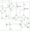
I'd appreciate any comments on this. I've attached a circuit diagram, but the format is poor, as I could not attach even small .jpg files (<500K).
Cheers
Arthur
Originally, the amp used the track of the presence control to bias the cathodes of the phase inverter (PI), so it had about 10V across it and 2 mA through it. I suspect this came about because the original designers wanted some negative feedback point, so split the tail resistor in two, with 10k at the top and 5K at the bottom. he feedback is injected in the middle, and actually goes to the grid of V3b via a 0.1 uF cap. Because of the high-impedance of the grid bias resistor, all auditable frequencies get to the grid of V3b. Thus the phase inverter is comparing the signal input from the tone stack with the negative feedback from the 16-ohm tap, and amplifying the difference.
The actual Presence control was still provided by a 0.1uF cap from the wiper to ground. When "up" the cap would short the negative feedback to ground (at least the mid to high frequencies), increasing the gain at these frequencies bu reducing the negative feedback to zero.
Although the power dissipated by the pot track isn't much (20 mW, and pots should handle 1/2 W), when the pot is rotated, the cap is subject to varying DC, so might cause a noise. (OK, it will charge and discharge pretty quickly, on the order of RC, or 5K x 100 nF = 500 us). Anyhow, I sort of suspected this could explain the "noisy" control, when moved.
Some time in the late 60's, the circuit was modified to put a 4K7 in parallel with the pot. I suspect this was a safety device, in case the pot's track became open circuit. The track would still have DC across it. It would also (about) half the negative feedback, maybe helping with stability at about 50 kHz.
In the 90's I adjusted the circuit to have this 4K7 resistor, but changed the cap's ground end to connect to the 4K7 (and the purple wire from the Perf Board). This removed the DC from the Pot. However, this did not give much range to the control; that is, the Presence was effectively set to a high setting. In the above factory modification, the pot was changed to 25K, and sometimes the cap to 0.68 uF.
So today I had a think about a better solution, without changing the pot. This was to keep the 4K7 resistor (I actually placed it between the purple-wire and ground turrets on the Perf Board, so it's nice and safe and secure. I then reverted to the original position of the 0.1uF cap, between ground and the wiper. Thus when the Presence is turned down, the cap is effectively fully out of circuit. II then connected the "hot" end of the pot to a new cap (DC blocking), whose other end went to the purple wire that originally went to the hot end. That is, I added a DC blocking capacitor to he circuit. This was 2.2uF 250V, but I am sure 1uF, 50V would do).
Anyhow, now:
1) the pot carries no DC current, nor has any DC voltage across it, so there's no charging up and down of the 0.1uF cap. No noise when altering the control.
2) The PI is now biased by the 4K7, which is a solid position
3) The presence control, when "down" is providing maximum negative feedback, and when "up" is shorting the mid/high frequency feedback to ground as before.
So it's *almost* back to a Black Flag, apart from the feedback is halved because the pot and the 4K7 are in parallel, forming a potential divider. This is probably good for stability, though. I might try reducing the feedback resistor again (although I have quite a few posts on increasing it from 27K to 74K, I think it might be OK at 47K now the pot and the 4K7 are in parallel.)
Oh and it sounds great! The presence adds presence.
I'd appreciate any comments on this. I've attached a circuit diagram, but the format is poor, as I could not attach even small .jpg files (<500K).
Cheers
Arthur
Attachments
Last edited:
")


