fer1991
Member
- Joined
- May 4, 2019
- Messages
- 62
- Reaction score
- 67
Hi everyone, I've got an oldy thing to discuss today. In the past I've taken my sc20h to the service to fix the fx loop (I'm leaving here a post where I talk about it) with very very bad experience with the service.
the link: https://www.marshallforum.com/threads/anyone-get-the-sc20-loop-fix-implemented.126766/
In all the things they did wrong, they messed up with the cable's order from the power supply going to the board. As I previously recorded a video for references, the second I saw that I asked them and they said that they were missorderer from the factory.
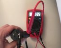
Since the whole job was poorly done, I reverted that, and even reinstalled properly the original resistors values they changed. But, is there any way to check if the transformer is properly connected?? Besides looking at my photos before the service or any other photo from google. Is there any way to measure with a multimeter the cables from the transformer and to know where they are supposed to be connected?? Thanks a lot everyone
the link: https://www.marshallforum.com/threads/anyone-get-the-sc20-loop-fix-implemented.126766/
In all the things they did wrong, they messed up with the cable's order from the power supply going to the board. As I previously recorded a video for references, the second I saw that I asked them and they said that they were missorderer from the factory.
Since the whole job was poorly done, I reverted that, and even reinstalled properly the original resistors values they changed. But, is there any way to check if the transformer is properly connected?? Besides looking at my photos before the service or any other photo from google. Is there any way to measure with a multimeter the cables from the transformer and to know where they are supposed to be connected?? Thanks a lot everyone
")