seeking for help, diy hiwatt 50, troublesome sound and abnormal voltage compared with schematic

Tao1

New Member
Joined
Sep 21, 2024
Messages
5
Reaction score
0
Hi
out of passion for pink floyd, i built a hiwatt 50 myself, this is the first time ever my life to build an amp. the first running was good, no spark. and i plugged my guitar, it works fine. But i always feel like the sound is not satisfied, it's not like the sound i heard from the demo sound from kit-rae. Because people all say big muff with hiwatt sounds fabulous.( my big muff with hiwatt sounds way worse than the demo sound from kit rae ) i use the same amp and muff setting as him.

so i was questioning if its because of my incorrect building.

I measured all voltages. All the voltage measurements are under the situation:
Mains and standby on, all preamp and power tubes are installed, connected into 8ohms speaker. All the voltages are measured to the ground. All the heater voltages are 6.8v( all the tubes work fine)

I found 2 problems.
The first problem: for my ecc81 phase inverter tube,the readings are
Pin1 298v
Pin2 89v
Pin3 84v
Pin6 290v
Pin8 84v
Which are massively different from the theoretical reading according to the schematic

The second problem is the v3 ecc83
Pin1 320v
Pin2(grid)87v
Pin3 84v
Pin6 226v (when I tap it with multimeter, a huge blow sound appearing from the speaker)
Pin7(grid) 0v
Pin8 1.8v

Why there’s voltage on pin2(grid) and no voltage on pin7(grid). I think grid should not have voltage for preamp tubes except for the phase inverter tube(ecc81). Is this normal?

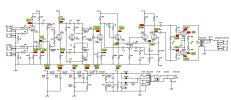
The schematic providing actual voltages is attached
I marked all the actual voltages in green and all the theoretical voltages on schematic.
Thanks for your help in advance
 

Attachments

  • Schematic.jpg
    Schematic.jpg
    412 KB · Views: 8

NickKUK

Active Member
Joined
Apr 5, 2024
Messages
152
Reaction score
135
Hi nick, i live in France, so it's 230v

Ahh you need to measure it at the point you measured the voltages.

My wife is French and I picked up a Phillips 1957 receiver a few years ago. Running it, it was clear it was higher end of the standard in Dunkerque which mean the heaters were on the hot side. Here in the uk we have +10%/-6% 230V and my wall voltage is usually 253Vrms rather than 230Vrms.

As the power supply is not regulated, as the wall voltage changes then the B+ voltages will change too.
 

Tao1

New Member
Joined
Sep 21, 2024
Messages
5
Reaction score
0
Hi
Thanks for your help. I just measured the wall voltage, it was 235v. It does explained part of the difference. But for the V4 ecc81, the plate voltages are way different from the theoretical voltage.
Ahh you need to measure it at the point you measured the voltages.

My wife is French and I picked up a Phillips 1957 receiver a few years ago. Running it, it was clear it was higher end of the standard in Dunkerque which mean the heaters were on the hot side. Here in the uk we have +10%/-6% 230V and my wall voltage is usually 253Vrms rather than 230Vrms.

As the power supply is not regulated, as the wall voltage changes then the B+ voltages will change too.
 

nortiks

Well-Known Member
Joined
Oct 17, 2023
Messages
443
Reaction score
695
IMO, nothing on your schem voltages looks obnoxious but the PI. Differences in line voltages, resistor tolerances and tubes can explain the rest.

If it were mine, I'd start with trying another tube in V4. If no fix, then move on to pulling V3 and probing the PI, triple checking the PI tail resistor values and connections. I'd measure with the presence control in various positions (it shouldn't matter). Double check XG connection.

Pin 6 of V3 goes straight to the PI input unattenuated via the 22n cap, so not surprised it makes a loud noise when you probe it when hot and connected to cab.
 

Tao1

New Member
Joined
Sep 21, 2024
Messages
5
Reaction score
0
IMO, nothing on your schem voltages looks obnoxious but the PI. Differences in line voltages, resistor tolerances and tubes can explain the rest.

If it were mine, I'd start with trying another tube in V4. If no fix, then move on to pulling V3 and probing the PI, triple checking the PI tail resistor values and connections. I'd measure with the presence control in various positions (it shouldn't matter). Double check XG connection.

Pin 6 of V3 goes straight to the PI input unattenuated via the 22n cap, so not surprised it makes a loud noise when you probe it when hot and connected to cab.
Thanks for your detailed help. I really appreciate it. i agree with you. the only difference I'm concerned is the plate voltages on ecc81, which are way higher/lower than the theoretical value.
the tube in v4(ecc81) is completely new one, i just bought it yesterday, so i think the problem is not on the tube.
1. Is it okay to pull V3 out and run the circuit without damaging the circuit?
2. Sorry for my poor knowledge, could you specify a little which tail resistors i should measure?
3. Checking connection, do you means the continuity?
4. i just measured the 10k resistor value near xg point, and it shows only 1.8k(i measure it in circuit, so could be not so accurate because of parallel or series), do you think this could be the reason why there's massive voltage difference on plate voltages of ecc81?
Thank you so much for your willingness to help
 

nortiks

Well-Known Member
Joined
Oct 17, 2023
Messages
443
Reaction score
695
Thanks for your detailed help. I really appreciate it. i agree with you. the only difference I'm concerned is the plate voltages on ecc81, which are way higher/lower than the theoretical value.
the tube in v4(ecc81) is completely new one, i just bought it yesterday, so i think the problem is not on the tube.
1. Is it okay to pull V3 out and run the circuit without damaging the circuit?
2. Sorry for my poor knowledge, could you specify a little which tail resistors i should measure?
3. Checking connection, do you means the continuity?
4. i just measured the 10k resistor value near xg point, and it shows only 1.8k(i measure it in circuit, so could be not so accurate because of parallel or series), do you think this could be the reason why there's massive voltage difference on plate voltages of ecc81?
Thank you so much for your willingness to help
If you have another ECC1 I'd pop it in and see. I have a pile of NOS and they give very different results, though not as much as you are seeing.
1) Many of the techs here say to do it, which is where I learned it from, and it does indeed prove useful to isolate things. I've done it on a number of amps but don't remember if I did it on my DR504. Probably not since its new...
2) Everything connected to pins 3,8 of V3 (cathodes) all the way back to ground and to XG.
3) Verify it is connected to the right adjacent parts and it has full continuity connections (sometimes a poor solder joint will look ok but really is defective and requires reflowing the solder, for example)
4) Depending on the adjacent circuitry, you often need to disconnect one side to get the measurement. PIA, but sometimes that's just what you have to do to narrow down the problem.

Hope this helps.
 

Tao1

New Member
Joined
Sep 21, 2024
Messages
5
Reaction score
0
If you have another ECC1 I'd pop it in and see. I have a pile of NOS and they give very different results, though not as much as you are seeing.
1) Many of the techs here say to do it, which is where I learned it from, and it does indeed prove useful to isolate things. I've done it on a number of amps but don't remember if I did it on my DR504. Probably not since its new...
2) Everything connected to pins 3,8 of V3 (cathodes) all the way back to ground and to XG.
3) Verify it is connected to the right adjacent parts and it has full continuity connections (sometimes a poor solder joint will look ok but really is defective and requires reflowing the solder, for example)
4) Depending on the adjacent circuitry, you often need to disconnect one side to get the measurement. PIA, but sometimes that's just what you have to do to narrow down the problem.

Hope this helps.
Thanks! I'll check them later when i'm back to home!
 
Top