• We are looking to make improvements to the Classifieds! Help us determine what improvements we can make by filling out this classifieds survey. Your feedback is very appreciated and helpful!

    Take survey

Simple Attenuators - Design And Testing

  • Thread starter JohnH
  • Start date
  • This site may earn a commission from merchant affiliate links like Ebay, Amazon, and others.

JohnH

Well-Known Member
Joined
May 31, 2008
Messages
6,155
Reaction score
5,062
Location
Wilton NSW
Thanks @Markus Bender , that's very interesting indeed. Based on that, it looks to be just a simple resistive attenuator with some tone shaping. Once turned down, the amp sees almost none of that reactance. Here's a quote from their site:

"We built into the RockCrusher a reactive load network for proper speaker-amplifier interaction. Rather than a purely resistive load like many of the other power attenuators on the market, the Rock Crusher ensures that the amplifier and speaker see each other in a proper relationship of impedance and inductive/capacitive reactance. This translates to a superior tone, regardless of level."

After looking at your diagram, I find those statements to be disappointing and inaccurate!
 

Marcomel79

Well-Known Member
Joined
May 3, 2021
Messages
1,822
Reaction score
2,675
Location
Oslo
So yesterday i got my Hammond box to build @JohnH's attenuator and today i was playing around to see the best layout for my 16Ohm build, based on Gene's diagram. I couldnt find the 50W 39Ohm resistor so i ordered a 20+18Ohm. Both 50W! Oh well.... Anyway, im still waiting for the inductor coil from China, hopefully it will be here soon...

So this is the first layout i tried, so as to maximize the space for the coil
587E9731-9D14-45F0-89F6-129414AAC2D7.jpeg C12DA666-8630-4D65-B4A7-F59F8721CA25.jpeg

And then i trid this one. There should be plenty of space for the coil.

843ED759-A646-4CB4-9E0A-CE3A48226FC7.jpeg 3796D0B2-8050-4108-8E16-E22F1A3F36FB.jpeg

By the way, that 100W 30Ohm resistor is just massive! I have some nice heatsink from an old power supply i no longer use which might come useful behind that big mutha.
 
Last edited:

JohnH

Well-Known Member
Joined
May 31, 2008
Messages
6,155
Reaction score
5,062
Location
Wilton NSW
I've also been thinking about how best to lay out the parts, so its easy to follow and easy to see and wire up.

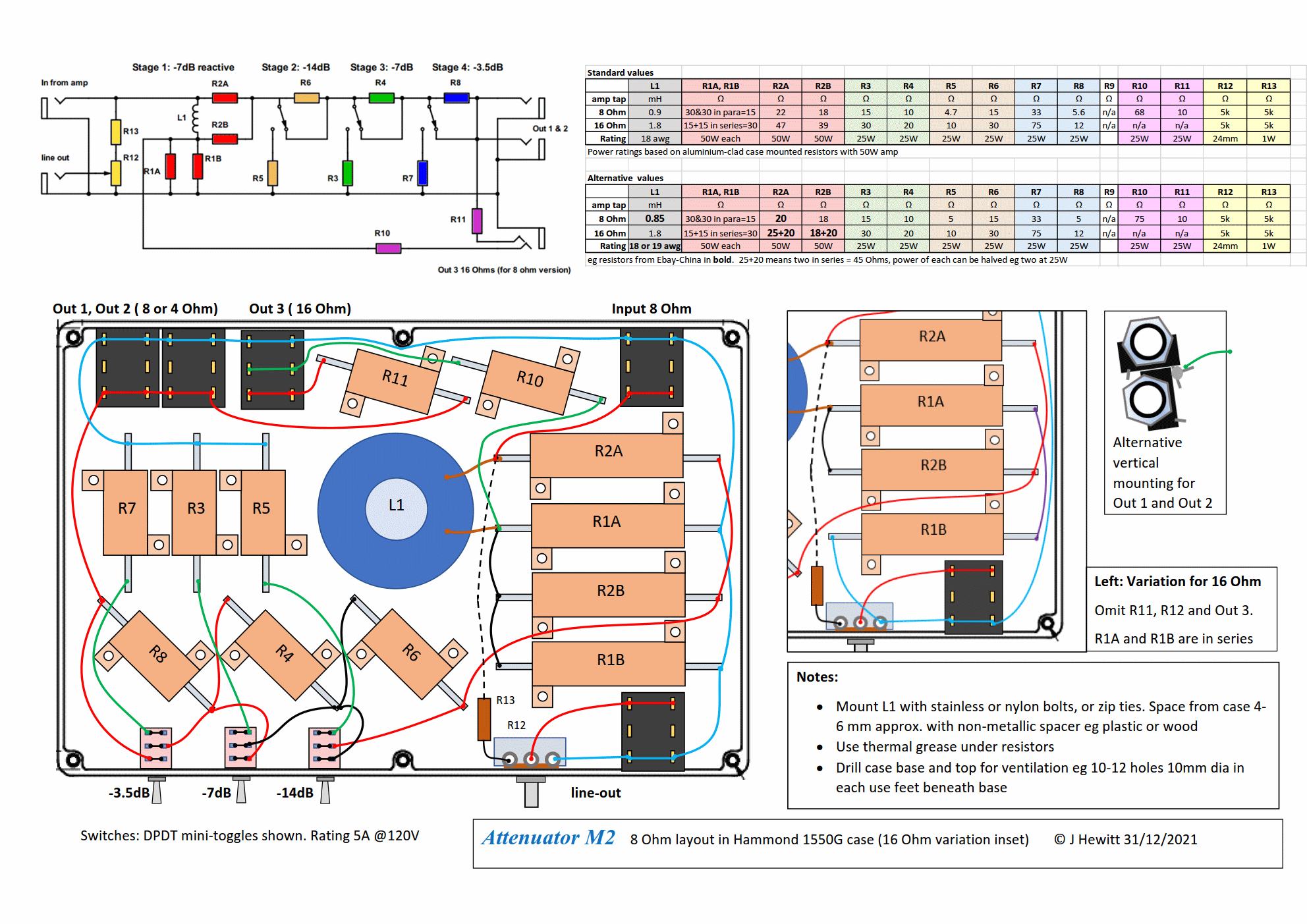
Here is a reasonably to-scale M2 layout, in a Hammond 1550G case:

(diagram edited 31/12/21)

It's basically an 8 Ohm M2, including the extra Out 3 for 16 Ohm output (which I find useful), and a basic line-out. There's a few new wrinkles, so I put the schematic and parts table on the diagram.

With long shipping times form China, more people seem to be using branded resistors such as Arcol. As noted above, the 100W ones get huge. So this uses a pair of 50W resistors for R1 (ie R1A and R1B). This may give a more compact and neater arrangement. Two 15's in series to make 30, or two 30's in parallel make 15. I separated the two R1A and R1B resistors to spread out the heat.

I moved the order of stages to go -14, -7, -3.5 db so that the logical front panel order matches the electrical and internal order. This is the same as Gene did above, and has been found to make no difference technically.

If you get jacks with 3x2 legs, then its important to connect to the primary lugs, not just to the switched ones, which are not used here. So to guard against error, the lugs are all shown linked across the jack so there's no risk. I show the jacks all in line, for ease of drawing. But what I actually build in mine is to put Out 1 and Out 2 vertically aligned, and you can rotate and engage/solder the lugs together as a preassembled unit - see inset diagram.

The case size is 222 x 146 and allows a fairly spacious layout, or by squeezing it up more, more add-on features.

The extra output and the line-out seem to be the most useful add-ons. I'd recommend against adding too many extras, but there are several others that have been developed in this thread:

  • options for variable input impedance (useful if you have several amps with no output tap values in common. But note you can already use different speaker ohms in the base designs. Also, you can easily build a couple of these units at different ohms to cover your options. Most ways to convert to different input ohms on one unit take off some more power, or get complex)
  • switching to reduce attenuation of Stage 1, to get a -3.5db setting (this can be useful if you want to have just a slight reduction. But with most rigs, even -7db is still loud. And, as a work around, you can set the unit as a load box in parallel with a speaker, to take off just 3 db at half the ohms amp tap)
  • foot-switching attenuation stages (useful if you want a lead/rhythm change, with no added drive, and can afford a few extra db's reduction.)
  • bass resonance circuit (M3 design - tests so far suggest that this makes very little difference to perceived tone when using a speaker, but may be desirable for when used as a load box with no speaker. The added cap and coil to convert an M2 to an M3 are relatively bulky and expensive. Note that when you run with a speaker, it will naturally make is own bass resonance without this circuit.)
  • full bypass switch (IMO, very few players really need this, unless you are setting levels with no or very little attenuation. After a few tests, most will either use the attenuator to attenuate, or not use it if its not wanted. A full bypass switch is handling the full amp power, so the chances of setting it up or operating it wrongly are significant)
  • fan cooling (the designs listed here, in a thick AL box are good for up to about a 50W amp with no fan. A few running amps at 100W have used them however)
Note that with the line-out option, even if you don't use the pot, you may well find that the signal level at the final attenuated speaker output is at a good level to feed into a mixer line-in, with no dedicated line-out. In any case, an IR loader or cab-sim will be needed to replicate a credible speaker tone.
 
Last edited:

brad Messier

New Member
Joined
Dec 25, 2021
Messages
8
Reaction score
1
Hi Brad and welcome to our thread. The main thing would be to confirm that the amp is based on a 4 ohm output, which I assume it is if that's the the speaker Ohms. If so, you can build M2, with all values x 1/2 (compared to the8 Ohm one) to make a 4 ohm version. i can find a list of best standard values for that. If you have an 8 Ohm tap, you can also use an 8 Ohm M2 and its fine to run it with an 8 or a 4 Ohm speaker.

You can also reduce power ratings on resistors if you wish, or keep it at 50W spec for use with other amps.

On the M2 diagram, you may not want Out 3, and for this amp, you could choose to omit the -14db stage if you wanted.

Thanks for all the info. That new layout looks great BTW! So I can drop all of the resistor values by half, and go down to a 25W rating pretty safely.
Should I drop the value of the inductor coil down to .5mH? Looks like I have a couple of options .55, .5, and .45 in 20 AWG coils.
I am planning on dropping the Out 3, no real need. Any benefit to keeping the two outputs? I don't see any real need for two any time soon.
I will drop R5 and R6 from your older diagram and omit the -14db stage.
If I want to add in the line out do you suggest any adjustment to R12 and R13 values?

Thanks again, can't wait to get building!
 

JohnH

Well-Known Member
Joined
May 31, 2008
Messages
6,155
Reaction score
5,062
Location
Wilton NSW
Thanks for all the info. That new layout looks great BTW! So I can drop all of the resistor values by half, and go down to a 25W rating pretty safely.
Should I drop the value of the inductor coil down to .5mH? Looks like I have a couple of options .55, .5, and .45 in 20 AWG coils.
I am planning on dropping the Out 3, no real need. Any benefit to keeping the two outputs? I don't see any real need for two any time soon.
I will drop R5 and R6 from your older diagram and omit the -14db stage.
If I want to add in the line out do you suggest any adjustment to R12 and R13 values?

Thanks again, can't wait to get building!

Hi Brad,

For a low power, 4 Ohm build, id suggest as follows:

R1: just use one, as with earlier diagrams, 8 Ohms (or 8.2)
R2A: 12
R2B: 10
L1: 0.45mH (0.5mH is OK), use 18 gage for lower resistance:
R3: 8 (or 8.2)
R4: 5.6
R5, R6 - omitted
R7: 18
R8: 2.7

If you are doing the line-out, the output voltage will be fairly low since its 4 Ohms and low power. so i suggest to reduce R13 from 5k to say 1.5k

Sure just 1 output is fine, unless you want to try different cabs. If you built Out 3, it would be for using an 8 Ohm cab (resistors 27 and 4.7), but no need if you don't want that.

Good luck with your build.
 

Marcomel79

Well-Known Member
Joined
May 3, 2021
Messages
1,822
Reaction score
2,675
Location
Oslo
Hey @JohnH, what do you think of this layout? Will the 47Ohm resistor get too hot to be standing right under the input/output jacks (top left)?
B863AD18-C831-44B4-9D88-206CB6ED6779.jpeg

Initially i was gonna order the resistors from China but after shipping and import tax costs (i live in Norway), i decided to buy locally for actually less money. I bought all 1% tolerance. The coil was 1mm, which is the closest to 18awg.

That will be the last to arrive...look forward to put it together and try it.

Thank you so much for sharing this FREE OF CHARGE!

Marco
 

JohnH

Well-Known Member
Joined
May 31, 2008
Messages
6,155
Reaction score
5,062
Location
Wilton NSW
hi @Marcomel79 , I think it will be ok. R2A and R2B don't get very hot really. I'd suggest to think through your wiring and access to solder lugs before committing though!
 

Marcomel79

Well-Known Member
Joined
May 3, 2021
Messages
1,822
Reaction score
2,675
Location
Oslo
hi @Marcomel79 , I think it will be ok. R2A and R2B don't get very hot really. I'd suggest to think through your wiring and access to solder lugs before committing though!
I will be sure to check it three times! Thank you for the prompt answer John
 

bikescene

New Member
Joined
Nov 9, 2020
Messages
8
Reaction score
7
I am finally going to build an attenuator based on the 50W M2 design after a long bout of procrastination. I will be using 100W, 50W, and 25W Arcol resistors. Do you guys have any tips on applying the optimal amount of thermal paste onto resistors? I’ve only ever used thermal paste on older PC builds, not heat sink resistors.

I thought I saw pictures in this thread showing the application of paste onto the resistors, but I haven’t been able to find them again.

I’ve drilled out a Hammond 12”x8”x2” enclosure that I had laying around. I just received a Dayton 0.9mH 18AWG inductor from Parts Express. I am just waiting on some nylon hardware before I proceed.
 

Mcentee2

Active Member
Joined
Jan 17, 2020
Messages
312
Reaction score
162
Location
York,UK
I am finally going to build an attenuator based on the 50W M2 design after a long bout of procrastination. I will be using 100W, 50W, and 25W Arcol resistors. Do you guys have any tips on applying the optimal amount of thermal paste onto resistors? I’ve only ever used thermal paste on older PC builds, not heat sink resistors.

I thought I saw pictures in this thread showing the application of paste onto the resistors, but I haven’t been able to find them again.

I’ve drilled out a Hammond 12”x8”x2” enclosure that I had laying around. I just received a Dayton 0.9mH 18AWG inductor from Parts Express. I am just waiting on some nylon hardware before I proceed.


Good luck with it all, a bit of careful planning goes a long way I think!

I used some grey computer CPU paste, can't recall the brand at the moment, and basically just squeezed the tube and applied it to the base of the resistor and swirled it round roughly so it was present across the whole surface, still blobby though.

Then just bolted the resistor to the enclosure. Whilst tightening it all up the paste is squeezed and spreads out somewhat to leave a residual thin layer between resistor and enclosure.

Of course though, you end up with a fair bit of paste squeezed out of the sides to somehow mop up with a cloth or wipe, and it can get quite messy as it's sort of sticky floppy stuff.

I prefer having too much and messy, than not putting enough on.
 

bikescene

New Member
Joined
Nov 9, 2020
Messages
8
Reaction score
7
Good luck with it all, a bit of careful planning goes a long way I think!

I used some grey computer CPU paste, can't recall the brand at the moment, and basically just squeezed the tube and applied it to the base of the resistor and swirled it round roughly so it was present across the whole surface, still blobby though.

Then just bolted the resistor to the enclosure. Whilst tightening it all up the paste is squeezed and spreads out somewhat to leave a residual thin layer between resistor and enclosure.

Of course though, you end up with a fair bit of paste squeezed out of the sides to somehow mop up with a cloth or wipe, and it can get quite messy as it's sort of sticky floppy stuff.

I prefer having too much and messy, than not putting enough on.

Thanks. I was trying to Google general tips on applying the paste and was having no luck. I'll need to make some cut outs that are the same sizes as these resistors and experiment with the amount.

I 've got the chassis all drilled out already. I need to double check my planned wiring before I start, since I'm deviating a bit. I will be adding an additional fixed 7dB stage since I will only be using the attenuator at home.

AVvXsEjQIsw8HZ_oEVi8oujD99N04KXVaMbXF04BAl2ZvMgtJ-0l6QtbtIlTKZjUnZbgMpdyMPaiOjCjdcMFj7JzAv9C7zQfEzDM_FbvRopQPt7o77k9sERV3TxeMpQ9DRn4lTaW2G3Avs2BGuuC6HJ2AGu11HDrY2ZvBUniAay7haFAtZJuTK6rX8hX7uLy=s1148
 

JohnH

Well-Known Member
Joined
May 31, 2008
Messages
6,155
Reaction score
5,062
Location
Wilton NSW
Hi @bikescene , welcome to our thread. It looks like you are doing some good careful planning.

For the thermal paste, the ideal is to end up with the thinnest possible layer that covers the full base of the resistor. I smear it thinly then as I place the resistor, move the resistor a little side to side while pressing, then do up bolts. It all helps though it's not as critical as for a CPU.

You could practice on one, then pull the resistor off to see how complete the coverage is. A thinner layer is better than a thick one. The best paste is that with the highest conductivity, I think that's usually the grey stuff that has aluminium in it.
 

diego_cl

Member
Joined
Jan 10, 2021
Messages
57
Reaction score
31
I am finally going to build an attenuator based on the 50W M2 design after a long bout of procrastination. I will be using 100W, 50W, and 25W Arcol resistors. Do you guys have any tips on applying the optimal amount of thermal paste onto resistors? I’ve only ever used thermal paste on older PC builds, not heat sink resistors.

I thought I saw pictures in this thread showing the application of paste onto the resistors, but I haven’t been able to find them again.

I’ve drilled out a Hammond 12”x8”x2” enclosure that I had laying around. I just received a Dayton 0.9mH 18AWG inductor from Parts Express. I am just waiting on some nylon hardware before I proceed.

I've no idea if I'm doing it correctly, but this is how I do it. I know it works, because the attenuator I made before goes very hot with a 50W amp (see video):
https://imgur.com/EL3ICMA

I spread it like peanut butter with a palette knife, not too thick, but also not too thin... I try to cover the base of the resistor with just enough paste to hide the aluminum. The bolts make the rest. Then I use a q-tip for cleaning, sometimes with isopropyl alcohol if it's too messy.

This is my M2 tool kit:
bAqsEag.jpg


- Thread cutting tap (M3)
- 3/32 drill bit
- Step drill bit (one of the best purchase I've ever made on Aliexpress)
- Cheap thermal grease from Aliexpress
- Stainless steel allen screws (M3, 5mm)

ms2JsNb.jpg


1vTcjKd.jpg


The 3/32 drill bit works great with the M3 tap and with the step drill bit.

The allen screws are great when the resistors are screwed sideways. Last time I had a lot of trouble driving phillips screws without enough space for the screwdriver. Besides, this screws are stainless steel and they don't break inside the threads like the ones I used before. It's a real pain in the ass to use a screw extractor and I had to do that like 3 times... didn't imagine this fragile aluminum case was able to break cheap screws so easily.

Right now I'm on my second build and this time I'm making sure the case has enough ventilation. Drilling is by far the most laborious job from the build, but this time it's going faster and better than the last time. I'm using a printed pattern, a punch tool, a 3/32 drill bit, a step drill bit and 3-in-one oil for protecting the drill bits. The holes ended up better aligned than last time.

7TkM738.jpg
 

bikescene

New Member
Joined
Nov 9, 2020
Messages
8
Reaction score
7
Thanks @JohnH and @diego_cl . It’s been very helpful to get some advice. The video was the perfect visual aid. I just mounted a few of the smaller 25W resistors after absorbing the feedback. I’ll move onto the larger resistors when I get the time.
 

Gene Ballzz

Well-Known Member
Joined
Feb 19, 2013
Messages
4,697
Reaction score
6,521
Location
Las Vegas, NV
HNCD!
But the AX is supposed to have greenbacks, were you surprised by the made in UK?

Thanks. I was trying to Google general tips on applying the paste and was having no luck. I'll need to make some cut outs that are the same sizes as these resistors and experiment with the amount.

I 've got the chassis all drilled out already. I need to double check my planned wiring before I start, since I'm deviating a bit. I will be adding an additional fixed 7dB stage since I will only be using the attenuator at home.

AVvXsEjQIsw8HZ_oEVi8oujD99N04KXVaMbXF04BAl2ZvMgtJ-0l6QtbtIlTKZjUnZbgMpdyMPaiOjCjdcMFj7JzAv9C7zQfEzDM_FbvRopQPt7o77k9sERV3TxeMpQ9DRn4lTaW2G3Avs2BGuuC6HJ2AGu11HDrY2ZvBUniAay7haFAtZJuTK6rX8hX7uLy=s1148


While your drawing is well done, it does not clearly illustrate three lugs on each switch. Can you confirm they are actually three lug, SPDT, ON-ON switches?

Thanks,
Gene
 

Marcomel79

Well-Known Member
Joined
May 3, 2021
Messages
1,822
Reaction score
2,675
Location
Oslo
Hi @JohnH, last night i finished your 16 Ohm attenuator. The coil hasnt arrived yet, so @Gene Ballzz suggested i use it without in the meantime. It reads 16Ohm on the dot!

I only had a chance to try it on my DSL5C and it sounds amazing. Put the amp on its sweet spot and now i have all these different levels of attenuations to play with! I cant imagine how much better it will be when the coil will be in place, im looking forward to it.

Here are some pictures of the build:

9BB92651-C93F-4BF5-A741-62C12D64A48A.jpeg 1BFAE5C2-0276-4596-BAC7-ED9848D5D7B9.jpeg 8A3EE770-0ED2-42F6-97DC-1DFE6DF0DB6A.jpeg

The lugs of the mini toggle switches were really tiny so i came up with this solution by cutting the sides of the lugs, allowing the buss wire to be soldered in place. This way there would be more space for the 18awg wire to be soldered, following Gene's layout. A bit extra work but i totally enjoyed the build.


158E082A-C42E-467E-AC67-6721130865B0.jpg F9F8E593-2F2E-4F8C-AE71-4A5AF8BAC831.jpg 24BE648B-1250-4458-92FC-1B9F119557CA.jpg


A massive, massive thanks to you John for sharing your work and being so helpful answering whatever questions we throw at you. I take my hat off to you sir.
Couldnt be happier with the result!

Ill post an update when the coil arrives.

Marco
 
Last edited:

JohnH

Well-Known Member
Joined
May 31, 2008
Messages
6,155
Reaction score
5,062
Location
Wilton NSW
Hi @Marcomel79 , that's a very nice build! And a clever way with the switches. I've also come to the view that those mini-switches are a good option, if you can deal with their small size.

The basic tone of what you have so far is probably very good. The coil may make it match a tad better. But mainly, listen for it's effect when you drive the power hard, you may get more dynamics and sizzle, varrying as the notes decay. It's a subtle effect, but if you get it, you'll know!
 

Marcomel79

Well-Known Member
Joined
May 3, 2021
Messages
1,822
Reaction score
2,675
Location
Oslo
Hi @Marcomel79 , that's a very nice build! And a clever way with the switches. I've also come to the view that those mini-switches are a good option, if you can deal with their small size.

The basic tone of what you have so far is probably very good. The coil may make it match a tad better. But mainly, listen for it's effect when you drive the power hard, you may get more dynamics and sizzle, varrying as the notes decay. It's a subtle effect, but if you get it, you'll know!
It sounds amazing already John! Like i said, i cant imagine its gonna be better with coil since it sounds SO good already without ! The DSL5C comes with a 5 to 0.5W power reduction switch which i never use because it sounds horrible. THIS is what Marshall should use!
 
Last edited:

bikescene

New Member
Joined
Nov 9, 2020
Messages
8
Reaction score
7
While your drawing is well done, it does not clearly illustrate three lugs on each switch. Can you confirm they are actually three lug, SPDT, ON-ON switches?

Thanks,
Gene

I am using Carling 2FB53-73 SPDT On-On switches. I was originally only using the drawing to lay out components as they will be oriented. I quickly added some wiring afterwards, so I’ll have a visual reference to keep track of my wiring. I do see how it looks a bit incomplete without a good view of all 3 lugs of the switch.
 

Gene Ballzz

Well-Known Member
Joined
Feb 19, 2013
Messages
4,697
Reaction score
6,521
Location
Las Vegas, NV
@Marcomel79
I think you're going to find that all tone is well retained at all attenuation settings with what you currently have. What will come back, when you're coil arrives, is the tactile feel and response, making it all seem even a bit more natural. There is little as pleasing as enjoying your amp at it's "Sweet Spot" without having family and friends angrily screaming "TURN IT DOWN!" It will be interesting to see how you finish up the external cosmetics!
Great Job On Another Succesful Build & Happy New Year!
Gene
 

Latest posts


Top