-
We are looking to make improvements to the Classifieds! Help us determine what improvements we can make by filling out this classifieds survey. Your feedback is very appreciated and helpful!
Take survey
You are using an out of date browser. It may not display this or other websites correctly.
You should upgrade or use an alternative browser.
You should upgrade or use an alternative browser.
Simple Attenuators - Design And Testing
- Thread starter JohnH
- Start date
This site may earn a commission from merchant affiliate links like Ebay, Amazon, and others.


matttornado
Well-Known Member
- Joined
- Mar 14, 2012
- Messages
- 1,900
- Reaction score
- 1,510
ah ok. thanks for answering my question!hi @matttornado , thanks for staying with us!
Sadly Line 'IN' or Return is not something that can really be included in a passive attenuator. All the commercial units that do it are based on active re-amping, where you can deal with line level signals then feed that to an amp. The signals that would be coming in from the effects are far to high impedance and small signal to mix with the low impedance speaker-level signals in a passive attenuator.
Gene Ballzz
Well-Known Member
Hello Again. I watch this thread from time time after building mine a few years ago when the thread started. I have a Line Out on mine and that works great and was easy to implement. But what If I want a line out Return like an effects loop? How would we bring the LIne Out back in?
Being able to add an effects loop would be the icing on the cake for me. As of now, I use the line out to feed effects then to a second amp.
@matttornado ,
FYI & FWIW, before life with The @JohnH attenuators, I used a Weber MiniMass to do a two amp, wet/dry rig. It had a post attenuator line out that I used to drive the input of an effects unit (Lexicon MX300) and out of the Lexicon into the effects return of an MG100HDFX amp This bypassed the preamp of the MG amp. It was by far the best and most natural sounding way to do delay, etc. An added benefit was that even though the preamp of the "wet" MG was bypassed, it still allowed me access to the onboard effects of reverb, chorus, flanger and delay. It was fantastic in many/most ways, EXCEPT setup, tear down and wiring on a daily basis was a royal P.I.T.A. Having the line out after the attenuator circuit allowed me to controlled a balanced volume for both amps, all from the attenuator.
Just Sharin'
Gene
AndersHall
New Member
- Joined
- Jan 25, 2023
- Messages
- 7
- Reaction score
- 2
I can add my plan:ah ok. thanks for answering my question!
I'm just about to be finished with my build, I will post some information regarding the fan here, and the whole build in the other thread with finished attenuators.
I have a line-out, and I plan to later build a second box connecting to the line-out, with a couple of passive loops incl one stereo. I'd use this for e.g. IR loader and effects, and then have a small class D amp module inside, either just circuit board or with housing, stereo or two mono, using DC or line voltage - just home usage so nothing very powerful is needed for me at the moment, but even powerful modules seem cheap on Amazon.
That's something that could be done in a single box with the attenuator as well, to give you the opportunity to use the JohnH with speaker for the dry, plus effects and reamping for the fx signal, or just in load box mode with reamping for the main+FX signal. That might be a solution to what you would like to have. Not much more complex than the basic build I think.
Others, feel free to comment on the possibilities and potential pitfalls.
Hey all,
I was about to pull the trigger to buy parts to make an l-pad attenuator for my 15 watt Silvertone 1482, when I stumbled across 175 pages of holy-diy-attenuator-johnh brilliance. So I've been researching. My goal is to be able to run the amp wide open without losing friends and neighbors. Doesn't have to be whisper quiet. The amp already trends dark (generally tone knobs are kept at 100%), and I was worried about it only getting darker w/ the Lpad.
A few questions:
1. Is the m2 a much better idea than an L-Pad for a 15 watt amp that runs dark? (I have a hunch I know the answer).
2. The silvertone has a 4 and 8 ohm tap. I've wired jacks for both. When overdriven, I think it sounds better on the 4 ohm (which matches the internal speaker). For cleaner sounds, it is amazing at 8 ohm, run through my 8 ohm 410. Is there a way to build the m2 so it can be selected to be fed by a 4 ohm or 8 ohm amp? Is this complex? (I know feeding different ohm speakers isn't an issue). I also have other 8 ohm amps (50-60w) which I could use it for. But the primary purpose is helping the silvertone do its thing.
3. Is there a simple, smaller version of the m2 I could build, just for a 15 watt amp at 4 ohm? I have a hunch there is, but I haven't been able to piece it together yet. (1/2 the values for 8 ohm m2, but what about the fact that the wattage is so low to start? Is there more to delete?) Curious to hear folks thoughts!
Thanks all. I'm super excited to have found this.
JohnH
Well-Known Member
Hi @parsnip , you have found the right thread! Welcome to our project.
The M2 can be built at any or 2, 4, 8 or 16 ohms. The values for 2 and 4 are on a small table within the first post.
It is possible to add a front-end to adjust for different amp Ohms, and the various output options in post 1 deal with different speaker Ohms if needed. The front end adds three parts, and its in the thread, I can find it. But, for your set up, I reckon you'll be better to build a dedicated 4ohm M2, and then a dedicated 8Ohm one.
Although the ohms conversions work well to preserve tone, each time you convert either at the front or the output, you lose up to 3dB of max power on top of the minimum attenuation.
Also, the most basic M2 circuit (top diagram in post 1) works very well and is very simple to follow as a build.
Lots of people are using the basic 50W spec for M2 attenuators to run 20W Marshall amps, so your 15W isn't much less. So I'd suggest build it as specced. It may get warm but it won't need a fan at 15-20 W. There's not much to simplify about it, unless you know that you don't need the full attenuation range. But it's hard to be sure so you might as well build all the stages.
If you then do an 8 ohm build for your larger amps, you might add a fan and then it will deal with them easily. Then you could also consider if any other features are useful.
And yes, it will sound way better than any Lpad circuit!
Johnh! Thank you for this. I've been researching since I wrote, and what you are saying now makes a lot of sense to me. I'm also astounded at all that's gone into this.
My current plan is to start with a dedicated 4 ohm m2. Am I correct in just following the specs across the "4 ohm" row in the table on page 1? (.45 coil, then 8 or 8.2 ohm, 100 w resistor in r1, then a 12 and 10 ohm 50 watt, then down to 25 watt for r3-8 (8-8.2; 5.6; 5.2; 8-8.2; 18; 2.7)?
I hope you won't mind me asking another couple of questions. Your generosity and enthusiasm is pretty astounding here, and I don't want to ask too much.
First, I want to confirm you would advise against reducing those wattage ratings. Given that I'm running this just w/ a 15 watt amp, I was considering working with smaller resistors in R1 (50?) and 2A and 2B (25?). This might make the final product a little smaller, and some of the parts easier to find.
I've been looking, and some of the resistors with particular ohm values are hard to find/source. Those that are difficult in 1% tolerance, are often available in 5%. Is that an acceptable substitution?
In particular, the largest, 8-8.2 ohm 100w resistor, which I imagine is most important, seems unavailable where I'm looking (US) in a 1% tolerance. Would it be preferable, given that it is for a 15 watt amp, to go for a 1% tolerance, but a 50 watt rating, or a 5% at 100 watts?
Last but not least, I'm finding .45 air coil at 20awg, but not 18. Is that acceptable (again, given the watts of the amp, I'm a little less concerned, but I don't want to under build and have heat issues or failure).
Thanks again for all!
JohnH
Well-Known Member
hi @parsnip
Really it's no problem reducing the power ratings if you really want to dedicate it to the 15W amp or less. My thinking was its the same work and not much more $ to build for 50W and so have a more versatile unit, but no biggie. 5% spec is fine for resistor values. I'd stick to 18 awg for the coil, particularly for a 4ohm build which runs higher currents than 8 or 16. The ohms of the coil is part of the design. I'll get back to you further on options for the coil ....
BTW..where are you in the world?
JohnH
Well-Known Member
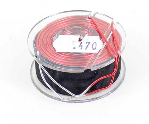
....for example, these from Parts Express and Madisound are close enough:
https://www.parts-express.com/Jantzen-1191-0.44mH-18-AWG-Air-Core-Inductor-255-226?quantity=1
 www.madisoundspeakerstore.com
https://www.parts-express.com/Jantzen-1191-0.44mH-18-AWG-Air-Core-Inductor-255-226?quantity=1
Madisound 0.47 mH 19 AWG Air Core Inductor
0.47mH Inductor 19 awg Air Core Medium Bobbin 48mm D x 23mm T DCR .34 OHM
www.madisoundspeakerstore.com


JohnH
Well-Known Member
I'd suggest to test with a meter to see if red is getting positive and black negative. Could also touch the fan wires to a 9v battery to see if it spins. I find those dc connectors hard to be sure of without testing to check which pin does what.
JohnH
Well-Known Member
well, we are running a 12v fan at 9v, which normally work work fine and nice and quietly. Do you have any source of 12v just for a test? And, I'm sure you've checked the pos and neg polarity?
")
Thanks for the above @JohnH ! That's helpful. I'm in NY, near the CT border. About 2 hrs north of NYC.
So I'll go for the original m2 specs for 4 ohm. I actually figured out how to run my main squeeze 60w amp at 4 ohm as well, so I think this will work for both.
For this build, is there a min. enclosure size you'd recommend? Putting together an order for tomorrow, and I'm hoping to get it right the first time around! I am hoping for one that will be fairly compact to sit on the silvertone when playing out. Looking at the hammond 1550e that Osman used on p 81. (Its 6.732"L X 4.764"W, by 2.169"H) I'm going very pared down (just in, out, 3 switches), so I'm crossing my fingers it will fit. Curious if I should go bigger though.
Also, for one resistor (5.6 ohm 25 watt in R4) I'm having trouble tracking it down without placing a separate order at another supplier, or going to China for long lead times. Do you think a 20 or 25 watt ceramic would work? (I can't post links yet, but there is a rectangular white ceramic style rated at 25W, and a tubular green ceramic style rated at 20W)
Thanks again for all. You and Gene are pretty amazing resources.
Last but not least: @Gene Ballzz I've seen in this thread you were doing some experimenting re: screws, cutting threads into resistors, etc. Have you landed on a favorite method and attending parts?
Last edited:
JohnH
Well-Known Member
hi @parsnip , best to hear from @Gene Ballzz about the best enclosures for these builds.
Thanks! Any opinions on having a ceramic resistor in the mix?Thanks for the above @JohnH ! That's helpful. I'm in NY, near the CT border. About 2 hrs north of NYC.
So I'll go for the original m2 specs for 4 ohm. I actually figured out how to run my main squeeze 60w amp at 4 ohm as well, so I think this will work for both.
For this build, is there a min. enclosure size you'd recommend? Putting together an order for tomorrow, and I'm hoping to get it right the first time around! I am hoping for one that will be fairly compact to sit on the silvertone when playing out. Looking at the hammond 1550e that Osman used on p 81. (Its 6.732"L X 4.764"W, by 2.169"H) I'm going very pared down (just in, out, 3 switches), so I'm crossing my fingers it will fit. Curious if I should go bigger though.
Also, for one resistor (5.6 ohm 25 watt in R4) I'm having trouble tracking it down without placing a separate order at another supplier, or going to China for long lead times. Do you think a 20 or 25 watt ceramic would work? (I can't post links yet, but there is a rectangular white ceramic style rated at 25W, and a tubular green ceramic style rated at 20W)
Thanks again for all. You and Gene are pretty amazing resources.
Last but not least: @Gene Ballzz I've seen in this thread you were doing some experimenting re: screws, cutting threads into resistors, etc. Have you landed on a favorite method and attending parts?
JohnH
Well-Known Member
Not really a technical problem with a ceramic there, just ugly, and you cant fix it to the chasis for heat spreading (its designed for air cooling). Im surprised its not available though, since 5,6 Ohm is one of the common values in most resistor ranges. 20 or 25W is fine - especially since your only running a 15W amp.
But what can you get in the aluminum, maybe a bit higher? then put a higher value, lower power ceramic piggy-backed in parallel across it. eg a 6 Ohm or a 6,8 Ohm, with a 100 Ohm or 33 Ohm ceramic respectively? Or can you get a 5 Ohm aluminum (and adjust R3)
But what can you get in the aluminum, maybe a bit higher? then put a higher value, lower power ceramic piggy-backed in parallel across it. eg a 6 Ohm or a 6,8 Ohm, with a 100 Ohm or 33 Ohm ceramic respectively? Or can you get a 5 Ohm aluminum (and adjust R3)
Thanks again John. I hope I'm not overthinking it. It looks like I can get a 5.6 ohm rated for 50W. Would that work?
Or I can get a 5.0 rated for 25W and adjust R3 (though I'm not sure in which way it should be adjusted.). I think I may just be bad at buying small electronic parts on the internet...
Or I can get a 5.0 rated for 25W and adjust R3 (though I'm not sure in which way it should be adjusted.). I think I may just be bad at buying small electronic parts on the internet...
JohnH
Well-Known Member
5.6 @ 50w seems like the easiest option. no problem with that.
Similar threads
- Replies
- 5
- Views
- 131
- Replies
- 5
- Views
- 544