• We are looking to make improvements to the Classifieds! Help us determine what improvements we can make by filling out this classifieds survey. Your feedback is very appreciated and helpful!

    Take survey

Simple Attenuators - Design And Testing

  • Thread starter JohnH
  • Start date
  • This site may earn a commission from merchant affiliate links like Ebay, Amazon, and others.

Gene Ballzz

Well-Known Member
Joined
Feb 19, 2013
Messages
4,697
Reaction score
6,521
Location
Las Vegas, NV
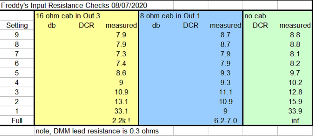
I'm just curious, how are you measuring that so exactly? AC Voltage with a multimeter, or..?


I was looking at your inductors and wondering if the coils are isolated? ie: is the metal coil touching the chassis directly? Or is the red color some insulator coating and the wire is under that?

Freddy G is a highly experienced and advanced recording/studio/live sound engineer and likely has access to measurement accuracy that mere plebes can only dream of. My apologies to Freddy if I'm sharing too much?

And it kinda looks as though he may have put some sort of plastic isolator/insulator between the coils and the case. Yes, the coil wires are at least lacquer coated/insulated, but I'm not sure I would want to depend on that, for the long term!

Just Sayin'
Gene
 

JohnH

Well-Known Member
Joined
May 31, 2008
Messages
6,157
Reaction score
5,062
Location
Wilton NSW
hi @Freddy G
Build looks great, all of that happened while I got a few hours sleep!

On the db ratios, there's a few things we can discuss. Yours is the first build I know of where the use of 16 Ohm speakers in an 8 ohm version is the main purpose of it. Usually its either been omitted or just adopted as a nice-to-have extra. I do have it on mine though, identical to yours and it works. But I haven't written as much about this feature. One of the things that happens is that when using the 16 Ohm speaker, there's about another 2db loss, so nominally -9 db for the first stage. So it could be just that though you are measuring a bit more. But, how are you measuring that difference? if its to compare the first stage output to the full bypass, would that involve the 16 Ohm speaker being sent through directly to the 8 ohm amp tap? If that's the case then it could explain the difference, but consider the mismatch 8 to 16 Ohms.

Although you are looking for a bit more volume, how is the tone that you are getting?

Things to try:

1. You can plug the 16 cab into the 8 output and run it in the -7db setting, its all safe and you should actually get a bit louder, like -6db. You may or may not hear a small reduction in high treble and maybe bass. If its OK, or you can compensate at the amp EQ then that's one good way. If you have them, the best controls on the amp for such EQ tweaking would be resonance and presence, or else something in the effects loop.

2. Using the 16 output again, You can bypass the 10 Ohm resistor R11. This will get stage 1 back to -7 db and bring back a bit of treble compared to option 1. Or if R11 goes to 5 Ohm Stage 1 is at -8 db with a 16 cab.

3. We can run a full resistance check on your build and compare it to mine and to the theory. Plug in the 16 Ohm cab to the 16 Ohm output as it is, then without the amp, measure resistance across the input in all settings from full bypass down to max attenuation. Allow for the resistance of meter leads by touching them together and subtracting that reading. Ill do the same on mine. They wont be identical but we should see if there is anything really different.
 

JohnH

Well-Known Member
Joined
May 31, 2008
Messages
6,157
Reaction score
5,062
Location
Wilton NSW
hi @telesto

As amateur shade-tree electronics tinkerers we may not have access to accurate db measurements in absolute terms. But we can make comparative measurements if a few ways. One trick I use for relative db's is to make some recording into the computer running Audacity. Then, I select a portion and tell it to 'amplify', and it will report how many db's it is going to offer me before clipping. If I do that on two traces I can subtract these values to get the db difference, to within 0.1 db. I've also used this method for the amp impedance measurements instead of a meter, working back from db ratios to voltage ratios.
 

Freddy G

Member
Joined
Mar 8, 2020
Messages
38
Reaction score
21
Could also be the cheap, cheesy, tiny switches (I used 'em too) screamin' for mercy, no matter what their ratings may claim to be! And then of course, there's those VERY affordable resistors made in Chinesiawanoreanam! There's also the thought of the inevitable magnetic fields created by the inductor coils in such close proximity to all else? I wish I were a rocket scientist, but I'm sadly not! Although the name of my current band is Rock It Science! :dude:

Just Thinkin'
Gene

Could be the components, but I doubt it...I think in a circuit like this they either work or they don't. I did however think it might be a good idea to separate the two coils so proximity to each other would not cause problems. Rock It Science....I love it!

I'm just curious, how are you measuring that so exactly?


I was looking at your inductors and wondering if the coils are isolated? ie: is the metal coil touching the chassis directly? Or is the red color some insulator coating and the wire is under that? I would guess it's probably not a good idea to have the raw coil touching the chassis, if that's what's happening there.

I was playing around with some other configurations (my own different configs, not John's design), and switching the coil in and out, and noticed sometimes I would have some squealing with the coil in, but when I switched it out I never had it. If I were you, I would look at the coil first. If it's really causing problems, try to un-solder it and bypass it with just a straight wire and see if it stops. At least you can rule it in or out as the source.

How do I measure? I just stuck a mic in front of the speaker, recorded a riff into a looper and played it back while I recorded it at all the different attenuations. I know that my mic pres are very linear because I built them, they have tons of headroom. Also I sent a sine wave signal through the amp and recorded it as well, just to cross check.

Yes the coils are isolated although it's hard to tell from the pics....good eye! But regarding the squealing, as I said, all I have to do is ground the chassis and it cures it. So I guess the simplest and most effective fix is right in front of me!

My apologies to Freddy if I'm sharing too much?

Just Sayin'
Gene

Nah....all good!

hi @Freddy G
Build looks great, all of that happened while I got a few hours sleep!

On the db ratios, there's a few things we can discuss. Yours is the first build I know of where the use of 16 Ohm speakers in an 8 ohm version is the main purpose of it. Usually its either been omitted or just adopted as a nice-to-have extra. I do have it on mine though, identical to yours and it works. But I haven't written as much about this feature. One of the things that happens is that when using the 16 Ohm speaker, there's about another 2db loss, so nominally -9 db for the first stage. So it could be just that though you are measuring a bit more. But, how are you measuring that difference? if its to compare the first stage output to the full bypass, would that involve the 16 Ohm speaker being sent through directly to the 8 ohm amp tap? If that's the case then it could explain the difference, but consider the mismatch 8 to 16 Ohms.

Although you are looking for a bit more volume, how is the tone that you are getting?

Things to try:

1. You can plug the 16 cab into the 8 output and run it in the -7db setting, its all safe and you should actually get a bit louder, like -6db. You may or may not hear a small reduction in high treble and maybe bass. If its OK, or you can compensate at the amp EQ then that's one good way. If you have them, the best controls on the amp for such EQ tweaking would be resonance and presence, or else something in the effects loop.

2. Using the 16 output again, You can bypass the 10 Ohm resistor R11. This will get stage 1 back to -7 db and bring back a bit of treble compared to option 1. Or if R11 goes to 5 Ohm Stage 1 is at -8 db with a 16 cab.

OK...haha full disclosure! I used the 8 ohm output to do my testing. Here in my shop I have a 2 X 12 cab loaded with 16ohm speakers to make an 8ohm cab. But I won't be using that cab with my amps or these attenuators. I have two single 12, 16ohm cabs at my rehearsal studio that I use for my rig.

The tone is great with the stage 1 reactive load. Just too much of a cut.

3. We can run a full resistance check on your build and compare it to mine and to the theory. Plug in the 16 Ohm cab to the 16 Ohm output as it is, then without the amp, measure resistance across the input in all settings from full bypass down to max attenuation. Allow for the resistance of meter leads by touching them together and subtracting that reading. Ill do the same on mine. They wont be identical but we should see if there is anything really different.

That sounds like a great idea. I will do that. But I'm knocking off for the day, back tomorrow. Thanks guys!
 

JohnH

Well-Known Member
Joined
May 31, 2008
Messages
6,157
Reaction score
5,062
Location
Wilton NSW
Here's my resistance values:

input R 200707.gif

More than might be needed, but in the table above, there's DC resistance values at the input for a 16 Ohm cab into Out 3, and 8 ohm cab into out 1/2 and also no cab. Also I've put in the theoretical db attenuations at mid frequencies based on the component values.

The DCR columns are calculated values assuming perfect resistors and no losses in wire, contacts or meter leads (they do include coil resistance). The measured values are as measured by me today and are all higher by up to an Ohm or more, a variable amount. This is due to meter accuracy, component tolerances and all the other factors. I think its hard to get very good reliable values of small resistances on a basic meter. I don't think these variations are a problem, but I'm showing them just to illustrate that on another build, there may be other variations measured and it could still be all fine.

So if you try these, id expect some different variation but with the same trends. I think some of the most useful checks might be the ones with no cab, because the values do change distinctly and if there is something to be found, it may reveal it.

Another chart to look at is on page 1, where I recorded loops and then plotted out the db vs frequency graphs and also the differences in dbs to see the reduction steps. As you go from full volume down to the attenuated, the overall trend stays consistent but there is considerable wiggle happening between full and -7 db traces, which could be speaker breakup and room effects happening at loud volumes. So if you are interpreting db changes in terms of peak levels, then this could add to the attenuation values you are noting.


Lets explore what you have, and either find some build glitch in it, or else use it to figure out what should change to suit you better once you have tried it out with the full rig.
 
Last edited:

telesto

Member
Joined
Apr 29, 2020
Messages
67
Reaction score
8
How do I measure? I just stuck a mic in front of the speaker, recorded a riff into a looper and played it back while I recorded it at all the different attenuations.
Microphones...man, you rock-star guys get all the fancy equipment :bowdown:

LOL, just kidding ;). Ok, sounds pretty much the same like what John does, record a riff on a loop and mic it into a PC and see the levels there, makes sense. I tried measuring the difference with a SPL meter about 3 feet in front of the speaker, but I didn't really see it register much difference between some of the different attenuation settings :shrug:
 

Freddy G

Member
Joined
Mar 8, 2020
Messages
38
Reaction score
21
Here's my resistance values:

View attachment 76310

More than might be needed, but in the table above, there's DC resistance values at the input for a 16 Ohm cab into Out 3, and 8 ohm cab into out 1/2 and also no cab. Also I've put in the theoretical db attenuations at mid frequencies based on the component values.

The DCR columns are calculated values assuming perfect resistors and no losses in wire, contacts or meter leads (they do include coil resistance). The measured values are as measured by me today and are all higher by up to an Ohm or more, a variable amount. This is due to meter accuracy, component tolerances and all the other factors. I think its hard to get very good reliable values of small resistances on a basic meter. I don't think these variations are a problem, but I'm showing them just to illustrate that on another build, there may be other variations measured and it could still be all fine.

So if you try these, id expect some different variation but with the same trends. I think some of the most useful checks might be the ones with no cab, because the values do change distinctly and if there is something to be found, it may reveal it.

Another chart to look at is on page 1, where I recorded loops and then plotted out the db vs frequency graphs and also the differences in dbs to see the reduction steps. As you go from full volume down to the attenuated, the overall trend stays consistent but there is considerable wiggle happening between full and -7 db traces, which could be speaker breakup and room effects happening at loud volumes. So if you are interpreting db changes in terms of peak levels, then this could add to the attenuation values you are noting.


Lets explore what you have, and either find some build glitch in it, or else use it to figure out what should change to suit you better once you have tried it out with the full rig.

Thanks for doing this @JohnH !

just to be clear, is this your order of increasing attenuation?

Full
1- stage 4
2- stage 1
3- stage 1 & 4
4- stage 1 & 2
5- stage 1,2 & 4
6- stage 1 &3
7 -stage 1, 3 & 4
8- stage 1, 2 & 3
9- stage 1, 2, 3, 4
 

JohnH

Well-Known Member
Joined
May 31, 2008
Messages
6,157
Reaction score
5,062
Location
Wilton NSW
That seems right. There were a few electrical reasons for putting them in that order, the biggest was so that stage 4, which is the -3.5db goes last so that it can work on its own when wanted
 

Freddy G

Member
Joined
Mar 8, 2020
Messages
38
Reaction score
21
Spotted my wiring error! R6 was not connected to S3. Man.....I remember when I was drawing that layout and I continued the yellow line from R6 to S3 to S1 i thought to myself "self, maybe you better make the line a different colour from S3 to S1 or you might miss that that is a connection"
And wouldn't you know it, that's exactly what I did when I wired it. D'OH!
 

JohnH

Well-Known Member
Joined
May 31, 2008
Messages
6,157
Reaction score
5,062
Location
Wilton NSW
Good catch! That would leave R6, which is 15 Ohms, in series with the speaker and never bypassed, which would explain another -3.5db.

Might be worth stepping through those tests again at least for settings 1-4 and Full. It looks like there may still be something funky happening at the 16 Ohm output 3, where at full bypass it should read the speaker DCR of about 13-14 ohms and at setting 1 it should be around 15-16 ohms
 
Last edited:

Freddy G

Member
Joined
Mar 8, 2020
Messages
38
Reaction score
21
Good catch! That would leave R6, which is 15 Ohms, in series with the speaker and never bypassed, which would explain another -3.5db.

Might be worth stepping through those tests again at least for settings 1-4 and Full. It looks like there may still be something funky happening at the 16 Ohm output 3, where at full bypass it should read the speaker DCR of about 13-14 ohms and at setting 1 it should be around 15-16 ohms

I think it's all good. here are the new numbers:

attenuator check 09_07_20.jpg

Yeah, this thing sounds and feels just great! I'm so happy.

One last request @JohnH ....I would greatly appreciate it if perhaps you might plug in what the resistor values need to be if I wanted to change that first stage (reactive -7db) to a -5db cut!
 

Gene Ballzz

Well-Known Member
Joined
Feb 19, 2013
Messages
4,697
Reaction score
6,521
Location
Las Vegas, NV
@Freddy G & @JohnH
Let me see if I've got my understanding correct?
A) The minimum amount of attenuation that allows effective use of reactive, inductance coils is about -7db?
1) Any smaller level of attenuation (by itself) is not only not benefitted by inductance, but may actually introduce a degradation of tone, response and/or feel.
2) Smaller amounts of attenuation are best achieved through resistance only?​
B) It seems that the most important factor in John's design is a carefully maintained "ratio" of series and parallel resistance? This is one of the reasons why a continuously variable control becomes much more complicated and cumbersome to implement.
1) The choice of attenuation levels is somewhat dictated/limited by the standardly and conveniently available values of resistors in the required power/wattage ratings, although this could be adjusted through intelligent use of series and parallel arrangements to achieve specific resistance values?​
Please correct me John, if I'm out in the weeds with my cursory understanding.
Thanks,
Gene
 

JohnH

Well-Known Member
Joined
May 31, 2008
Messages
6,157
Reaction score
5,062
Location
Wilton NSW
Hi @Gene Ballzz , kinda like that!

It is difficult to keep everything in balance across a wide range. That's after realising what parameters need to be controlled. inductance and resistance seen by the amp and the speaker, and keeping them adequately in control as you step down. This is where the stepped stages work much better in a device that is simple to build, since they can be tuned for their specific job without requiring any exotic parts.

I find that the standard resistor ranges work OK provided ratios are maintained. Some of the online Chinese selections need a tweak at certain values, maybe two used together or one of higher value in parallel to bring it down.

But keeping the ideal balance is quite a trick. The current designs M and M2 start with the -7db stage which means that the sound is at 20% max power. The amp sees the attenuator and somewhere between 0 and 20% of the speaker. So the reactance at the amp is not varrying too much and can be optimised for the general range -7db down.

As we go towards a smaller first stage reduction, the speaker starts to appear more to the amp. This either needs the tone to be allowed to vary a bit wider, or it needs a different balance of components just for those settings alone. In the last couple of pages, I posted some single stage versions, tuned to just one attenuation, but these would not be ideal for a general full-range build.

The -3.5db stage in M working alone, as built by Freddy and myself, is a workaround, and it works quite well even though its only resistive. It would be a bit better with a bit more inductance in it, but it's not worth the complication of doing that just for this one setting, that is rarely used.

For @Freddy G we are talking about whether a couple more db s could be added to the maxmum attenuated volume, and I'm assuming this is to focus on use of 16Ohm cabs. I've got a few thoughts for next post....
 

JohnH

Well-Known Member
Joined
May 31, 2008
Messages
6,157
Reaction score
5,062
Location
Wilton NSW
No worries Gene!

Hi @Freddy G

It seems like your build is running on all cylinders now, and the resistance checks seem a lot more consistent than my own ones, being very close to the theory after allowing for meter leads. As such, its all in balance and for a box covering the full range that it does, I’ve not been able to further improve the design in the last year and a half, which includes trying to get another db or two as max attenuated volume. So to squeeze the design in that way, tends to make it pop slightly out of whack elsewhere. That could be OK, and its obviously most important that it works as well as it can for the range and use that you need.

I'm happy to play wit resistor numbers but, I think it would also be best to explore options that keep its core performance as intact as possible.

The extent that it reacts differently to different amps depends on the amp design. The most sensitive are those without negative feedback, such as one of mine, AC30’s, some small Fenders and Marshalls etc. What can you say about the output stages in your amps? Are they similar to others and do they have NFB? Any resonance and presence controls?

Reason for asking is that you might find some easy solutions, once you fire it up with the 16 Ohm cab. The as-designed Output 3 will cut another 2 db from a 16 Ohm cab, so it becomes -9db, relative to a 16 cab straight into a native 16 Ohm amp tap. But if you put that 16 cab into Output 1, then you get -6db. I hear that as an OK but not so edgy sound on my amps, and OUT3 corrects for that tone difference. But on a Marshall Plexi for example, it may make less difference ,and presence and resonance might also fix it. Worth a try. Using Out1 with a 16 cab is safe with stage 1 on (ie usually the -7db).

Also, when you run your whole rig in stereo, there’s another +3db right there from the second amp?

Here’s another way to wire it up, just thought of it:

I've talked before about using the attenuator as a load box, set to max attenuation, no cab in attenuator, to get a -3db setting when in parallel with the speaker. This was to use an 8 Ohm cab, and use a 4 ohm amp tap. Here’s the new idea. same setup, but using your 16 Ohm speaker direct to the 8 Ohm amp tap, and use the attenuator in parallel (ie if you have a second amp out socket or can rig one). For this, set the attenuator to setting 2, - 7db, and with no cab into it, it provides a credible reactive 16-ish Ohm load and you get -3db reduction. Thel load on the amp is now 16 from the speaker and 16 from the attenuator/load box so set, so 8 overall.

EDIT. I just tried this myself, it works. I used the 8Ohm tap on my VM, and plugged my 16 Ohm V30 cab into it and also the attenuator, set at -7db with no cab. Maybe that will get close to what you need, but anyway its another useful trick.
 
Last edited:

Freddy G

Member
Joined
Mar 8, 2020
Messages
38
Reaction score
21
No worries Gene!

Hi @Freddy G

It seems like your build is running on all cylinders now, and the resistance checks seem a lot more consistent than my own ones, being very close to the theory after allowing for meter leads. As such, its all in balance and for a box covering the full range that it does, I’ve not been able to further improve the design in the last year and a half, which includes trying to get another db or two as max attenuated volume. So to squeeze the design in that way, tends to make it pop slightly out of whack elsewhere. That could be OK, and its obviously most important that it works as well as it can for the range and use that you need.

I'm happy to play wit resistor numbers but, I think it would also be best to explore options that keep its core performance as intact as possible.

The extent that it reacts differently to different amps depends on the amp design. The most sensitive are those without negative feedback, such as one of mine, AC30’s, some small Fenders and Marshalls etc. What can you say about the output stages in your amps? Are they similar to others and do they have NFB? Any resonance and presence controls?

Reason for asking is that you might find some easy solutions, once you fire it up with the 16 Ohm cab. The as-designed Output 3 will cut another 2 db from a 16 Ohm cab, so it becomes -9db, relative to a 16 cab straight into a native 16 Ohm amp tap. But if you put that 16 cab into Output 1, then you get -6db. I hear that as an OK but not so edgy sound on my amps, and OUT3 corrects for that tone difference. But on a Marshall Plexi for example, it may make less difference ,and presence and resonance might also fix it. Worth a try. Using Out1 with a 16 cab is safe with stage 1 on (ie usually the -7db).

Also, when you run your whole rig in stereo, there’s another +3db right there from the second amp?

Here’s another way to wire it up, just thought of it:

I've talked before about using the attenuator as a load box, set to max attenuation, no cab in attenuator, to get a -3db setting when in parallel with the speaker. This was to use an 8 Ohm cab, and use a 4 ohm amp tap. Here’s the new idea. same setup, but using your 16 Ohm speaker direct to the 8 Ohm amp tap, and use the attenuator in parallel (ie if you have a second amp out socket or can rig one). For this, set the attenuator to setting 2, - 7db, and with no cab into it, it provides a credible reactive 16-ish Ohm load and you get -3db reduction. Thel load on the amp is now 16 from the speaker and 16 from the attenuator/load box so set, so 8 overall.

EDIT. I just tried this myself, it works. I used the 8Ohm tap on my VM, and plugged my 16 Ohm V30 cab into it and also the attenuator, set at -7db with no cab. Maybe that will get close to what you need, but anyway its another useful trick.

Thanks for all that. Very interesting ideas!
So, I was just spitballing when I asked about less than 7db cut. You're right, I will be running two amps in stereo. 7db might be just right, I won't know until I play the rig with the band. I should do that before I start asking to re-invent the wheel!

I have a 47k NFB resistor. Resonance circuit is fixed, 220K resistor in parallel with .0047 cap. Presence control 5k pot with a .1uf cap. I have been thinking about tweaking this though....maybe try a 33k or 27k NFB resistor. I'm finding that the time based effects in the FX loop are not quite as clean as I would like and hopefully more NFB (ie smaller value resistor) will clean it up but also it will knock off a db or two I think. Could be a win-win!
 
Top