• We are looking to make improvements to the Classifieds! Help us determine what improvements we can make by filling out this classifieds survey. Your feedback is very appreciated and helpful!

    Take survey

Simple Attenuators - Design And Testing

  • Thread starter JohnH
  • Start date
  • This site may earn a commission from merchant affiliate links like Ebay, Amazon, and others.

Shipwreck0316

New Member
Joined
Apr 3, 2021
Messages
16
Reaction score
2
@JohnH

I understand how to simplify the M2v using one input jack (16 ohm) and a toggle switch to change between 8/16 ohm modes. What has me scratching my head a bit is how the R12, R13 and L2 section doesn't affect the other two inputs since it appears to be in parallel with the 8 ohm load. Does it have to do with using a switched jack? Also I'm having a hard time sourcing the inductors. Where do most people go to purchase L1 and L2?
 

JohnH

Well-Known Member
Joined
May 31, 2008
Messages
6,156
Reaction score
5,062
Location
Wilton NSW
R12, R13 and L2 fofm a chain that is only connected permanently at one end, so until the other end is connected to something, it's doing nothing to the signal. The 8 ohm input doesnt connect to the floating end, so its not in play. The 16 ohm input connected its hot to the loose end, forcing all signal through it so it's impedance becomes part of the load. For 4 ohms, the loose end goes to the ring terminal of tbe jack, which grounds it only when a plug is inserted. Only one input is used at a time.

The coils are generally found where speaker parts are sold, since they are used in crossover networks. In the US, Madisound.com have them in 19 gage (ok for the 50W) and 16 gage (recommended for 100W). A wide range of values are available, but if you can't see 0.9mH, then 0.85mH is fine. We also know of places in the EU, UK and Australia.
 
Last edited:

iefes

New Member
Joined
Apr 6, 2021
Messages
11
Reaction score
4
Hi everybody, I came to the MarshallForum after I stumbled upon information about this gorgeous attenuator design by John and have since read quite a lot in this topic. I've built some amps so far and always wanted to find a nice attenuator design that wasn't too complex. I was about to build an attenuator based on Ken Fishers Airbrake but then got hooked by this thread here.

I've got two questions before I start buying parts and building.

I've got a large inductor laying around in my parts bin which has an inductance of 1.5 mH and will take 100W with ease. I'd love to use this but would prefer to build the 8 Ohm version. From a Spice simulation I ran, I can see that the impedance increase at higher frequencies starts a little "earlier" than with the 0.9mH inductor. Do you think this will be audible at all? Have you tried different inductances in an actual built setup?

Even though I find the design very elegant, I kind of don't like that it needs so many separate switches. I know this is nitpicking, but I was trying to wrap my head around other (not necessarily better) options. Here, each resistive stage has the shunt resistor in front of the series resistor, which is the same principle in the airbrake design. If I get this right, every stage is set up so that the impedance "as seen in both directions" is a constant 8 Ohms, no (for the 8 Ohm version)? Wouldn't it be possible to use an 8 Ohm L-Pad wired backwards instead of several resistive stages? If the wiper lug of the L-Pad was used as the input, the topology of shunt -> series resistors should be kept the same. This way it would be possible to control the volume by only one potentiometer and the impedance should still stay the same over the rotation. I'm not really sure if the L-Pad will provide a constant 8 Ohm when wired backwards, but if this was the case, it should work, don't you think? Like this there would be an initial 7dB reduction from the reactive stage and from there the Volume could be variably attenuated down to 0.

That's just an idea so I'd be happy to hear your opinions about it.

I'm looking forward to your thoughts!
 

JohnH

Well-Known Member
Joined
May 31, 2008
Messages
6,156
Reaction score
5,062
Location
Wilton NSW
hi @iefes and welcome to our thread,

On inductors, although its not so critical that everything needs to be within 1%, the value does make an audible difference and the values posted are the sweet spot, within about 10%. My early versions which had two inductors (still a good scheme) started with two equal inductors and i wasn't hearing the benefit of them. Then I did more maths and @Gene Ballzz built one and it came to life with about a 40:60 ratio between two coils. The current versions use one coil and get the same performance, balanced by two resistors. Out of all that, the conclusion is that the values make a difference and its better to use the best values. The coil is not expensive and suitable ones are easily available in most places.

The coil should be 18 gage wire, air cored. This is to stop saturation and keep a low resistance. So its not maxed out from a power handling standpoint, its also about its resistance

If your 1.5mH coil is 18 gage or thicker and is air cored, you can probably unwind it down to 0.9mH, if you have a way of working that out or of measuring inductance.

On the switching, Ive also thought a lot about using pots and l-pads, either way round. You could make something but its not going to keep the consistency we need. L pads are designed to maintain something not too far from 8 Ohms, as seen from the amp, and with quite a large margin, but they take no care at all of the impedance seen by the speaker. Turn them around and the problem is reversed. Also, in this design our target is 8 ohms seen by the amp but about 18-20 ohms seen by the speaker.

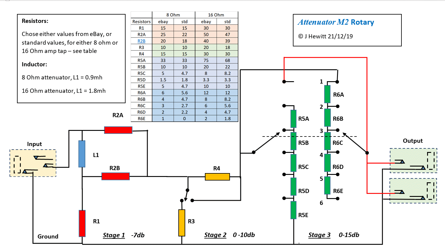
The best version of a rotary control is probably a rotary switch, if you can get one with good enough current handling. You can do a version where there's a fixed reactive stage, a toggled -7db stage (or a different value), then a rotary that does 0, -3.5, -7, -10.5, -14db.

But, the toggles are very simple and very robust and reliable, working on a binary system where each provides x2 the attenuation. And the switched steps of -3.5db are audibly very small. You might consider if you want to engage 3.5db more, or not, but its unlikely that you'd need to split it any finer.
 

Gene Ballzz

Well-Known Member
Joined
Feb 19, 2013
Messages
4,697
Reaction score
6,521
Location
Las Vegas, NV
Very well put sir! :applause: While not as elegant as could be, the multiple toggle system is very reliable. I have searched for rotary switches with 10 positions and enough poles to handle the task of providing every switched/switchable level from Bypass to -31.5db in -3.5db increments. Capable units, with enough current capacity cost as much if not more than the rest of the attenuator's bill of materials! The most current listed build seems the best so far, with alternative values, etc, is in post #1165.
C'est La Vie?
Gene
 

iefes

New Member
Joined
Apr 6, 2021
Messages
11
Reaction score
4
Hi @JohnH and @Gene Ballzz ,

thank you very much for sharing your thoughts! With respect to the inductor, I see that it would make sense to get the right value. I mean it probably depends on the impedance of the actual speaker you want to replicate, but I guess your design is very well tested and therefore I will try to use these values. An impedance rise starting at slightly lower frequencies might correspond to a more pronounced treble roll off? Can it be put that way or is this a over-simplification? However, I'll try to find out how I can measure the inductance of my coil and maybe try to remove a few windings from it to bring it down to 0.9mH. That's really a good idea, I didn't think about it before. Thanks for that!

I was playing a bit more using LTSpice last night and came to the same conclusion regarding the L-Pad. I simulated a backwards mounted L-Pad but it didn't give the desired results. I also simulated T-pads and various versions of cascaded L-Pads and such but none of the approaches seemed to yield good results.
I totally agree that using separate switches gives the most reliable and flexible solution, so that's definitely the best way to go. I too think that steps of 3.5dB are fine enough, for me steps of 6dB would be probably sufficient.
How would you wire the rotary that you suggested? You would have to switch between different stages rather than opening and closing switches in a layout of cascaded stages like in your single switch design, right?

Why did you choose to let the speaker see 18 - 20 ohms? I may have missed a post where you explained this, so if it exists, a link to that post would be appreciated.

I might as well think about a combination of your design and something along the lines of an Airbrake for the higher levels of attenuation, at whose supposedly the speaker doesn't interact so much with the amp anymore (?). I have two large wirewound potentiometers laying around anyway (50 Ohms, 1 of them 100W the other 200W) which could come in handy for this task.

Thanks heaps for your thoughts! This was very helpful. I'll definitely let you know when I have built the attenuator :)
Cheers
 

JohnH

Well-Known Member
Joined
May 31, 2008
Messages
6,156
Reaction score
5,062
Location
Wilton NSW
The inductance of the coil is based on matching measured impedance curves of typical Celestion speakers, which are all about the same for 12" types

A rotary version would be based on making one rotary stage, but using two poles to adjust the values, like this:


The 18-20 Ohms is based on measuring the actual equivalent output impedance of my amps. Some are lower and some are higher but this is a good mid range. Plus, due to some magic in the maths which Ive seen but is hard to explain, if you take these values as a basis, but use it with amps of different effective output impedances, it tracks the results very well. This may be why this attenuator has proven to work well with a wide range of different amps.

You can add as many stages as you like, but just make sure that the speaker always sees that consistent output impedance if you want consistent tone.
 

iefes

New Member
Joined
Apr 6, 2021
Messages
11
Reaction score
4
@JohnH thanks a lot for this diagram! I'll wrap my head around the different options and keep in touch :) I'm actually leaning towards the standard 8 Ohm version at the moment.

Thanks a lot so far!
 

ichocobo

Member
Joined
Jan 6, 2020
Messages
47
Reaction score
70
Hi @JohnH,
Just a few words to thank you for your GREAT, AWESOME, ABSOLUTELY SHOCKING attenuator design.
I've Built the M2 and was surprised how easy was to build. And tone is flawless once plugged in (vs Two Notes Torpedo Captor -20db setting on the SV20).

I have to confess that I'm still suspicious something eventually will go very wrong, simply because I can't believe it works so good with such little effort... (on my side, of course)!
 

tschrama

Well-Known Member
Joined
May 15, 2010
Messages
1,539
Reaction score
889
Location
Netherlands
...The 18-20 Ohms is based on measuring the actual equivalent output impedance of my amps. Some are lower and some are higher but this is a good mid range. Plus, due to some magic in the maths which Ive seen but is hard to explain, if you take these values as a basis, but use it with amps of different effective output impedances, it tracks the results very well. This may be why this attenuator has proven to work well with a wide range of different amps.....


My hesitation with this kind of attenuators is summarized in the following hints:

Do you want to emulate the output impedance of an guitar amp? Closed-Loop or Open-Loop? Imagine what happens to the output impedance of a clipping power amp. Or should an attenuators aim for presenting a speaker load to a power amp and feed the resulting voltage waveform to the actual speaker without interaction, thus presenting the speaker a close to zero source impedance.
 

JohnH

Well-Known Member
Joined
May 31, 2008
Messages
6,156
Reaction score
5,062
Location
Wilton NSW
Hi @JohnH,
Just a few words to thank you for your GREAT, AWESOME, ABSOLUTELY SHOCKING attenuator design.
I've Built the M2 and was surprised how easy was to build. And tone is flawless once plugged in (vs Two Notes Torpedo Captor -20db setting on the SV20).

I have to confess that I'm still suspicious something eventually will go very wrong, simply because I can't believe it works so good with such little effort... (on my side, of course)!

Great! thanks for the feedback.

There's nothing to worry about, it's brick-solid and very simple robust technolgy. The trick was in working out what it needed to do, and optimising the maths to make it happen.
 

JohnH

Well-Known Member
Joined
May 31, 2008
Messages
6,156
Reaction score
5,062
Location
Wilton NSW
My hesitation with this kind of attenuators is summarized in the following hints:

Do you want to emulate the output impedance of an guitar amp? Closed-Loop or Open-Loop? Imagine what happens to the output impedance of a clipping power amp. Or should an attenuators aim for presenting a speaker load to a power amp and feed the resulting voltage waveform to the actual speaker without interaction, thus presenting the speaker a close to zero source impedance.

What we know is, it works, based on showing the speaker a average value of an amp at small signals. What seems to happen is that as the amp changes its output impedance with different feedback, or harder driving, the attenuator responds to change its frequency response to suit due to the way the reactive front end is wired . This is demonstrated in analysis, but I can't explain it in words.
 

JohnH

Well-Known Member
Joined
May 31, 2008
Messages
6,156
Reaction score
5,062
Location
Wilton NSW
hi @tschrama , further to the above, if you look at post 915, 8th May 2020, on page 46. It explores how the design adapts to different amp output impedances. Before that, there's also a couple of posts about different design options on page 27.
 

mike_lawyer

Member
Joined
Sep 2, 2019
Messages
32
Reaction score
5
Any store other than Madisound recommended for obtaining the air core inductor? Their website lists the 0.85 19AWG inductor as out of stock. Thanks!
 

JohnH

Well-Known Member
Joined
May 31, 2008
Messages
6,156
Reaction score
5,062
Location
Wilton NSW
Hi Mike, these things are best found where loudspeaker components are sold. Im in Australia and I buy them here, but I see Parts Express in the US have this:

Jantzen Audio 0.90mH 18 AWG Air Core Inductor Crossover Coil (parts-express.com)

That one is of the type where its wound on itself without a bobbin. So you put something insulating under it, it could be wood, ideally a few mm thick to reduce eddy currents, then zip tie to the base of your case. Avoid steel screws.

also , I think Madisound do a 16 gage range, but there'll be many other places since some are from main manufacturers and some are wound by small makers.
 

mike_lawyer

Member
Joined
Sep 2, 2019
Messages
32
Reaction score
5
Any comparisons of this attenuator with PPIMV? I imagine the attenuator would stay truer to the sound because you would have no loss of negative feedback.

I am thinking of building a 50W Plexi with PPIMV that would allow some nice tweaking in conjunction with this attenuator.
 

JohnH

Well-Known Member
Joined
May 31, 2008
Messages
6,156
Reaction score
5,062
Location
Wilton NSW
Sure, and they'd work well together.

I designed it initially around my Vintage Modern, which is basically a jtm45 with an extra stage and a ppimv. it gets a bit shrill with mv less than about 4, and with the attenuator it can be turned up to find any sweet spot at any volume.
 
Top