• We are looking to make improvements to the Classifieds! Help us determine what improvements we can make by filling out this classifieds survey. Your feedback is very appreciated and helpful!

    Take survey

Simple Attenuators - Design And Testing

  • Thread starter JohnH
  • Start date
  • This site may earn a commission from merchant affiliate links like Ebay, Amazon, and others.

matttornado

Well-Known Member
Joined
Mar 14, 2012
Messages
1,900
Reaction score
1,510
So folks,

Having just built three of these units, I tested them extensively, in a sonic manner, as in no SPL meter! One was an M2/16ohm with an extra, tonally compensated 8ohm out and the other two were M2/8ohm with an added, tonally compensated 16ohm out. One of the M2/8ohm units has a fan installed! These made six of these units I've built! The first three were prototypes for testing, layout and reworks.

The test subjects were my Marshall SV20H head, a 16Ω 1960B, 4x12 with 98db Greenbacks and a 1965B 4X10 with 94db G10L-35s. I recorded a 1 minute-ish, cranking rhythm loop and for each test (except stepping through the stages) I let the loop crank at full attenuation for at least an hour or more. It should be noted that comparing a 98db speakers loaded cabinet to a 94db speakers loaded cabinet complicated the comparison, just a little bit.

Here are the sonic and heat results:
> Both the 8Ω and 16Ω units performed flawlessly, with no tonal artifacts and/or losses at all attenuation levels.
> On both units, the compensated out (for 16Ω on the 8Ω unit and 8Ω out on the 16Ω unit) retained all tone, but did indeed give just a tiny bit more attenuation (I'd guess around 1 or 2 db) than using a cabinet "native" to the unit's input impedance.
> All three units heated up pretty well (not burn your hand hot, but almost as hot as a fresh cup of coffee), but the one 8Ω unit with a fan, cooled down to just barely "luke warm" with the fan running!

My conclusion is that this attenuator design is "BY FAR" the best ever conceived, retaining all tone, feel and response throughout its range of operation! When properly ventilated and heat sinked, it requires no fan up to about 30 watts, fully cranked for long perioids of time. Anything above 35 watts and yup to 50 watts, fully cranked should utilize a fan!

Now, FWIW, the reason I've built/am building so many of these, is that every time I get one finished and folks hear/see it, someone wants to buy it! I use them all the time, so I need to have at least an 8Ω & 16Ω unit on hand, for my own use! Here ar pics of #4 & #5, and I'll get pics up of #6, once the fan guard/filters arrive and get installed! This is the formt I plan to use for all future 50 watt M2 builds, although, I've found some slightly more pleasing feet! Anyone interested in getting their hands on one of these, while avoiding the time/effort of building, can feel free to contact me privately, as custom features can be either added or deleted! I'm not a business and am not making these commercially, I simply want folks to be able to enjoy the liberation these units provide, for those not equipped to do a build themselves! They truly are the greatest thing since sliced bread!

Thanks 4 Looking!
Gene

M2/16Ω


Looks amazing!!!! I'd like to re house mine a well. Ttrying to find the perfect enclosure as I have a giant 300 watt resistor taking on the load at all times.
 

Gene Ballzz

Well-Known Member
Joined
Feb 19, 2013
Messages
4,697
Reaction score
6,521
Location
Las Vegas, NV
Hammond 1550J


I'm getting ready to work up a layout and drilling template and the 1550J is exactly what I was looking at! FWIW, I do some cool templates that can be printed on peel & stick project paper and stuck to the box for center punching and drilling. It would give a look similar to the pics in posts #2931 & #2934 of this thread, labeling/art work is up to you. Saves a bunch of time and layout hassle. It may take up to a week for me to get the layout done!

Knowing what part of the world you're in would help for parts sourcing suggestions! Also, reminding us of whether this is a 16Ω or 8Ω build would be helpful? Additionally, avoid the Vishay/Dale resistors from Mexico, as the mounting footprint is a little different than the TE and Ohmite/Arcol units. DigiKey currently has a better selection of "in stock" resistors available than Mouser, in TE Conectivity brand, and they ship almost anywhere for free, with a big enough order!


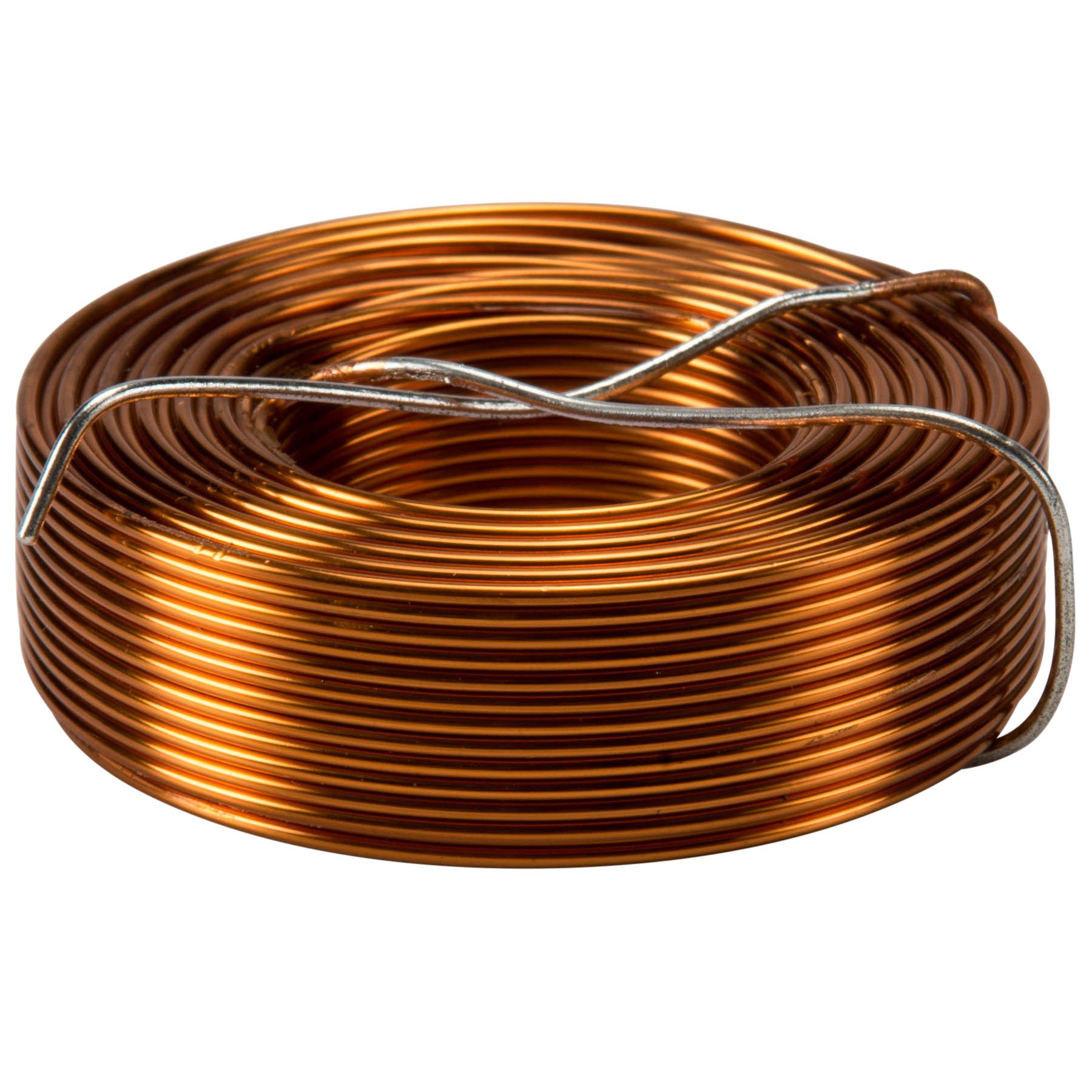
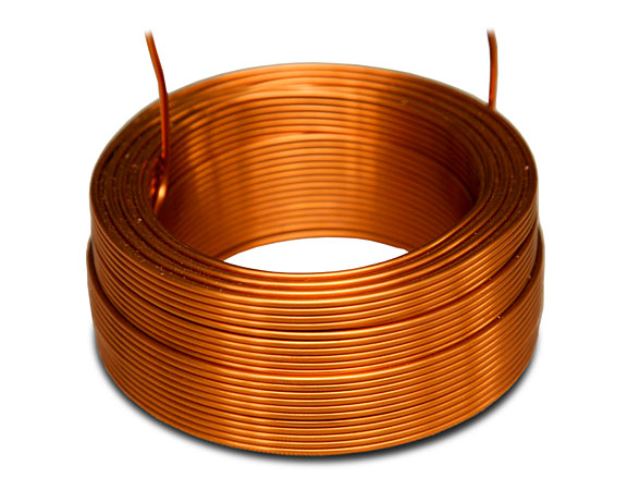
I think you should have something like this: 0,9 mH, 18 AWG, air core coil (for the 8 Ohm M2 version)

Switches look OK with SPDT ON-ON design and 10A rating at 250VAC (again for the normal M2 version).


Pietro is building a 100 watt (as my next build will be) so needs at least a 16 AWG coil. I think PartsExpress may be the most convenient source.


I personally prefer the bobbin wound units from folks like Madisound, but they don't sell a 0.90mH and the 1.0mH that could get unwound a little bit, is currently out of stock!


Just Attenuatin'
Gene
 
Last edited:

BlueX

Well-Known Member
Joined
May 5, 2020
Messages
2,703
Reaction score
5,676
Location
Sweden
but I'm having trouble finding the correct inductor.

Pietro is building a 100 watt (as my next build will be) so needs at least a 16 AWG coil. I think PartsExpress may be the most convenient source.
Here's a 0,9 mH, 15 AWG, version, from another European web shop if that's more convenient.

Since different versions are now built, here is the Jantzen webpage with an Excel file you can download. There you can filter on inductance, AWG, etc., to find the right item.

I then just google "Jantzen <item no>" to find a web shop where it's available. Seems like Jantzen's hifi coils are available with many different models in Europe.
 

pietro.castelli

Active Member
Joined
Aug 18, 2021
Messages
95
Reaction score
190
I'm getting ready to work up a layout and drilling template and the 1550J is exactly what I was looking at! FWIW, I do some cool templates that can be printed on peel & stick project paper and stuck to the box for center punching and drilling. It would give a look similar to the pics in posts #2931 & #2934 of this thread, labeling/art work is up to you. Saves a bunch of time and layout hassle. It may take up to a week for me to get the layout done!

Knowing what part of the world you're in would help for parts sourcing suggestions! Also, reminding us of whether this is a 16Ω or 8Ω build would be helpful? Additionally, avoid the Vishay/Dale resistors from Mexico, as the mounting footprint is a little different than the TE and Ohmite/Arcol units. DigiKey currently has a better selection of "in stock" resistors available than Mouser, in TE Conectivity brand, and they ship almost anywhere for free, with a big enough order!

Sweet! I would greatly appreciate the printable drilling layout when you are done! 😉

I’m based in Europe, so mouser is definitely convenient for me! Digikey is also fine.
I’d like to build the 8 ohm version with the additional 16 ohm output.

I’ve already identified all the necessary resistors from ohmite/arcol and they are sitting in my cart.
The 100w 18 ohm resistor unfortunately is out of stock at the moment, but I’ll wait a bit before ordering.

I just need to find alternatives for the switches as the one I’ve selected initially are very expensive!

I think I just miss the inductor but I’ll follow all the precious advices I’ve been given to source it!

Thanks so much Gene and also thanks to all the people who chimed in to help!
 

pietro.castelli

Active Member
Joined
Aug 18, 2021
Messages
95
Reaction score
190
Here's a 0,9 mH, 15 AWG, version, from another European web shop if that's more convenient.

Since different versions are now built, here is the Jantzen webpage with an Excel file you can download. There you can filter on inductance, AWG, etc., to find the right item.

I then just google "Jantzen <item no>" to find a web shop where it's available. Seems like Jantzen's hifi coils are available with many different models in Europe.

This is great! Thanks!
 

Gene Ballzz

Well-Known Member
Joined
Feb 19, 2013
Messages
4,697
Reaction score
6,521
Location
Las Vegas, NV
Sweet! I would greatly appreciate the printable drilling layout when you are done! 😉

I’m based in Europe, so mouser is definitely convenient for me! Digikey is also fine.
I’d like to build the 8 ohm version with the additional 16 ohm output.

I’ve already identified all the necessary resistors from ohmite/arcol and they are sitting in my cart.
The 100w 18 ohm resistor unfortunately is out of stock at the moment, but I’ll wait a bit before ordering.

I just need to find alternatives for the switches as the one I’ve selected initially are very expensive!

I think I just miss the inductor but I’ll follow all the precious advices I’ve been given to source it!

Thanks so much Gene and also thanks to all the people who chimed in to help!

For all the 100 watt resistors, you may want to try flea-bay for some of the vendors from chinesiawanoreanam, as they have a smaller footprint and are consiederably less pricey. There is often quite a lag for shipping, but the other conveniences make it worth the wait! A bit of time spent can find the best vendors that won't "bone" you on prices/shipping fees! I'm assuming that you've already caught on that the 200 watt R1 is best tackled by two 100 watt, 30Ω resistors in parallel, for your 8Ω build?

Part of my layout research will surround which is bet for the 50 watt resistors, two 25 watt in series and/or parallel or single 50 watt units. With the templates I'll provide, it's your choice whether you countersink the mounting holes or leave them for protruding screw heads. Also, we'll need to share real email addresses, as we have no good way to share pdf, tiff or png files here.

Just Helpin'
Gene
 
Last edited:

lordjester

New Member
Joined
Jan 27, 2022
Messages
8
Reaction score
10
Hi Folks,

I´m still not sure about the impedance thing. I built a 8 Ohm M2 (with 16 Ohm Option). I´m normally using it with a Magnatone Varsity, 8Ohm speaker output with an 8 Ohm speaker. No problem so far. If I use a second speaker, 8 Ohm at the second 8 Ohm speaker output of the M2, the amp sees 4 Ohms? Right? So , how can I use a second 8 Ohm speaker with the M2. Any mods for this? thanks, Lothar
 

JohnH

Well-Known Member
Joined
May 31, 2008
Messages
6,157
Reaction score
5,062
Location
Wilton NSW
I think maybe you meant to say “famous” and not “infamous”, when describing Fender amps, but I could be wrong. Maybe you just don’t like Fender amps?

Thanks both for your precious help! This forum is absolutely great!

I’ve a couple additional questions, If I may:

-what’s the purpose of having out1 and out2 in the circuit? Just connecting two speakers in parallel?

-would it be theoretically possible to add one more resistive stage to achieve a total attenuation close to 37-38db?

Cheers

Pietro

Hi Folks,

I´m still not sure about the impedance thing. I built a 8 Ohm M2 (with 16 Ohm Option). I´m normally using it with a Magnatone Varsity, 8Ohm speaker output with an 8 Ohm speaker. No problem so far. If I use a second speaker, 8 Ohm at the second 8 Ohm speaker output of the M2, the amp sees 4 Ohms? Right? So , how can I use a second 8 Ohm speaker with the M2. Any mods for this? thanks, Lothar
Hi Lothar,

You can do this with an M2. Plug both cabs into the two 8 Ohm outputs , and although the attenuator sees 4ohm, it still shows the amp an 8 0hm load because Stage 1 is still there, so its quite safe.

You may hear a very small tone difference at 4ohms, with about a db more treble and bass compared to mids . If you'd like to adjust for that slight difference, you can put a 39 Ohm resistor across the speaker output either via a switch or you can engage it using another jack. I suggest to try as it is first though .
 

JohnH

Well-Known Member
Joined
May 31, 2008
Messages
6,157
Reaction score
5,062
Location
Wilton NSW
hi @lordjester Actually, apologies but the right value for this 4ohm case is 20 or 22 Ohm . A 25w would be fine, 10w is also ok with a 50w amp.
 

MikeD2

New Member
Joined
Aug 20, 2022
Messages
4
Reaction score
1
I've also been thinking about how best to lay out the parts, so its easy to follow and easy to see and wire up.

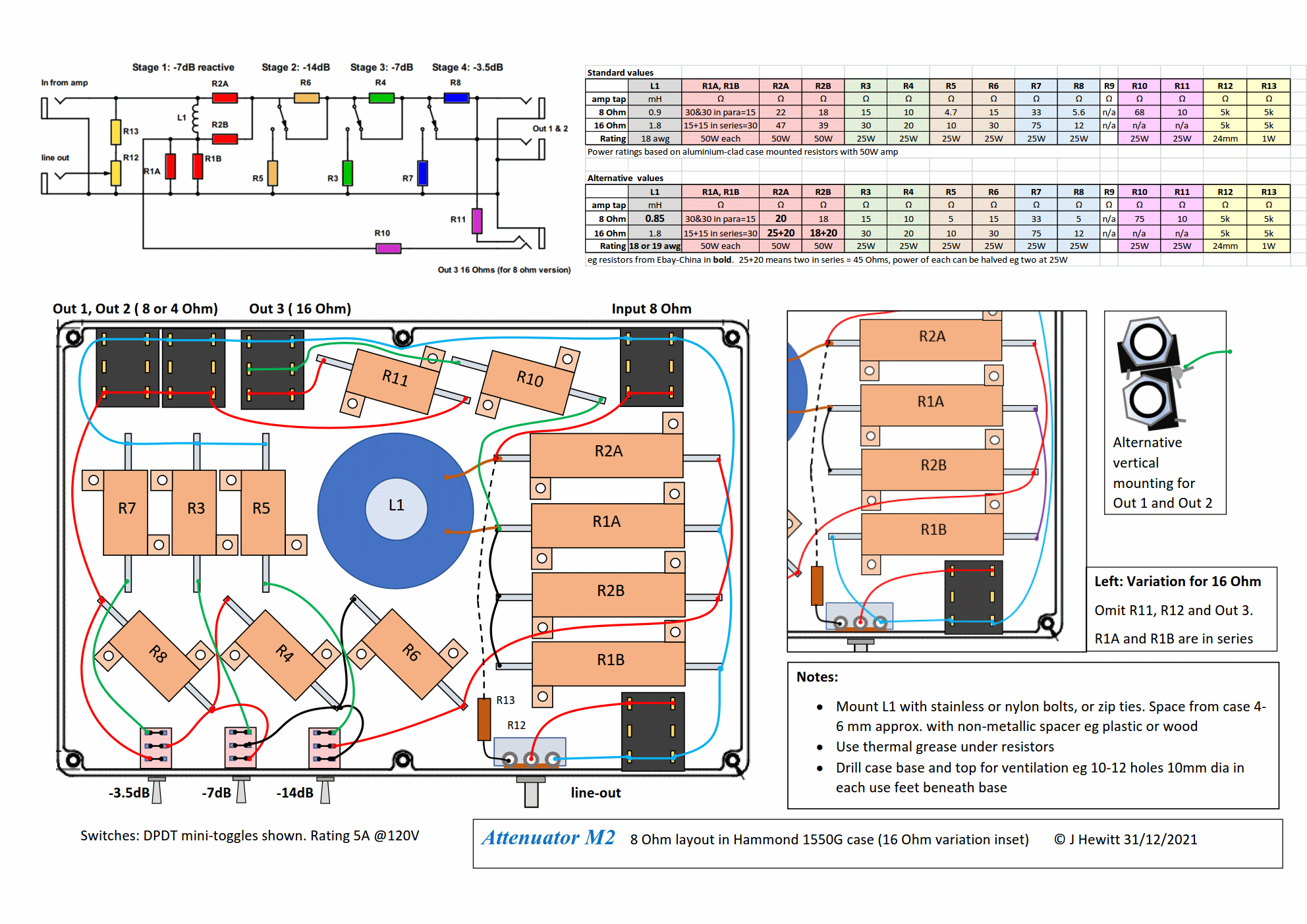
Here is a reasonably to-scale M2 layout, in a Hammond 1550G case:

(diagram edited 31/12/21)

It's basically an 8 Ohm M2, including the extra Out 3 for 16 Ohm output (which I find useful), and a basic line-out. There's a few new wrinkles, so I put the schematic and parts table on the diagram.

With long shipping times form China, more people seem to be using branded resistors such as Arcol. As noted above, the 100W ones get huge. So this uses a pair of 50W resistors for R1 (ie R1A and R1B). This may give a more compact and neater arrangement. Two 15's in series to make 30, or two 30's in parallel make 15. I separated the two R1A and R1B resistors to spread out the heat.

I moved the order of stages to go -14, -7, -3.5 db so that the logical front panel order matches the electrical and internal order. This is the same as Gene did above, and has been found to make no difference technically.

If you get jacks with 3x2 legs, then its important to connect to the primary lugs, not just to the switched ones, which are not used here. So to guard against error, the lugs are all shown linked across the jack so there's no risk. I show the jacks all in line, for ease of drawing. But what I actually build in mine is to put Out 1 and Out 2 vertically aligned, and you can rotate and engage/solder the lugs together as a preassembled unit - see inset diagram.

The case size is 222 x 146 and allows a fairly spacious layout, or by squeezing it up more, more add-on features.

The extra output and the line-out seem to be the most useful add-ons. I'd recommend against adding too many extras, but there are several others that have been developed in this thread:

  • options for variable input impedance (useful if you have several amps with no output tap values in common. But note you can already use different speaker ohms in the base designs. Also, you can easily build a couple of these units at different ohms to cover your options. Most ways to convert to different input ohms on one unit take off some more power, or get complex)
  • switching to reduce attenuation of Stage 1, to get a -3.5db setting (this can be useful if you want to have just a slight reduction. But with most rigs, even -7db is still loud. And, as a work around, you can set the unit as a load box in parallel with a speaker, to take off just 3 db at half the ohms amp tap)
  • foot-switching attenuation stages (useful if you want a lead/rhythm change, with no added drive, and can afford a few extra db's reduction.)
  • bass resonance circuit (M3 design - tests so far suggest that this makes very little difference to perceived tone when using a speaker, but may be desirable for when used as a load box with no speaker. The added cap and coil to convert an M2 to an M3 are relatively bulky and expensive. Note that when you run with a speaker, it will naturally make is own bass resonance without this circuit.)
  • full bypass switch (IMO, very few players really need this, unless you are setting levels with no or very little attenuation. After a few tests, most will either use the attenuator to attenuate, or not use it if its not wanted. A full bypass switch is handling the full amp power, so the chances of setting it up or operating it wrongly are significant)
  • fan cooling (the designs listed here, in a thick AL box are good for up to about a 50W amp with no fan. A few running amps at 100W have used them however)
Note that with the line-out option, even if you don't use the pot, you may well find that the signal level at the final attenuated speaker output is at a good level to feed into a mixer line-in, with no dedicated line-out. In any case, an IR loader or cab-sim will be needed to replicate a credible speaker tone.
Hello everyone -
New to the forum. Looking forward to the M2 build with the line-out option - gathering parts now. One question I had is: does it matter if the potentiometer is linear or log taper?
PS: Thanks to everyone on here, (especially John H, otherwise I's still be running my Ceriatone ODS at probably 40 watts at home - not a good idea).
 

JohnH

Well-Known Member
Joined
May 31, 2008
Messages
6,157
Reaction score
5,062
Location
Wilton NSW
hi @MikeD2 and welcome to our thread.

Linear and log pots of the same value will give the same range. But log may offer more control to set the level that you need. Also given that you'll need to adjust the pot to suit the amp setting plus the input range of whatever you are connecting to. And, if the signal is too hot overall, the fixed resistor or resistors could be changed.
 

MikeD2

New Member
Joined
Aug 20, 2022
Messages
4
Reaction score
1
hi @MikeD2 and welcome to our thread.

Linear and log pots of the same value will give the same range. But log may offer more control to set the level that you need. Also given that you'll need to adjust the pot to suit the amp setting plus the input range of whatever you are connecting to. And, if the signal is too hot overall, the fixed resistor or resistors could be changed.
Thankyou John, appreciate your help! Off to AliExpress :)
 

GeorgeLG

New Member
Joined
Aug 22, 2022
Messages
2
Reaction score
0
Thanks for all the work done on this massive thread. I want to build an 8 ohm reactive load. Can someone point me to the place in this discussion where the best design is using the most readily available component values and a source for the high powered inductors and resistors? Dealing with chemo and I just don't have the energy to read this entire discussion. Thanks in advance,

George
 

JohnH

Well-Known Member
Joined
May 31, 2008
Messages
6,157
Reaction score
5,062
Location
Wilton NSW
hi @GeorgeLG , welcome to our thread

Happy ro help! Maybe if you could describe some more about what you'd like it to do? Reactive Load boxes generally are to replace a guitar speaker and provide a line-out signal to go to a cab-sim, Impulse Response loader and/or mixer or recording software, ie an actual guitar speaker is not involved, except possibly after another power amp. It's focus is just to show the amp an impedance vs frequency curve similar to a guitar cab.

Our designs here are Attenuators, which also show the amp a reactive load, but then include circuitry to step that down to feed a guitar speaker. You can use them without a speaker, just as a load, but the design focus is based on use with a speaker and that's what they are optimised for. Post 1 of this thread has the basics covered, see design M2

A guitar speaker impedance changes with frequency It hits the nominal ohms value at around 400 or 500 hZ. Above that it rises due to the inductance of the voice coil . And below this, there is a strong bass peak due to resonance, at around 80 to 120 hz.

It's this low resonance that can be the main difference with loadboxes vs our designs. To properly create the bass resonance in a load box with no speaker needs a big cap and a large coil. The best reactive load boxes eg by Suhr, include this. Our M2 Attenuator design does not have this, instead, we let the real speaker develop it itself. This saves the most expensive parts, but it needs a speaker. This approach works very well in the attenuator.

We can use M2 as a loadbox, safely and effectively but since the lineout doesn't have a bass peak, a bit of bass compensation downstream may be needed. Or, we have M3 that has these parts.

The bass peak is very narrow, sharply around just a few low notes on a guitar. So it's actually not that significant for most of the guitars range

So what's your intent?

1. You could build our M2 to use with a guitar speaker, with a line-out for when you don't use a cab, and maybe tweak the bass when you just use line-out.or,
2. Can add parts to make it M3, to show the amp a bass peak, or
3. As M2, but no speaker out just a load and add bass if needed (inexpensive and simple, just a few parts) or
4. As 3, with bass peak circuit.

Related questions are, what amps do you want to use it with? (Power and output ohms), and where in the world are you wrt ordering parts in your region?

If you'd like to read up more just on reactive load boxes, this is a great thread on TGP, which helped a lot with our designs:

https://www.thegearpage.net/board/index.php?threads/aikens-reactive-dummy-load.1072793/

All the best!
 

redberon2003

Member
Joined
Feb 9, 2010
Messages
59
Reaction score
65
Decided to build one of these in a 100w version using the minimum number of resistors instead of math because lazy………also wasn’t happy with the 200w 30ohm selection so I decided to just get a 300w

……….that 300w is a real honker lol80CD1A3B-3934-490E-85F9-EA9EDCB44032.jpeg
 

JohnH

Well-Known Member
Joined
May 31, 2008
Messages
6,157
Reaction score
5,062
Location
Wilton NSW
Hammond cases are good, get one that is generously sized (maybe 250mm length) and plan the layout carefully. For 100W, the concensus here is thst you need a fan. A brushless dc fan designed for 12v but running at 9v from a wall warts is a good option. And plenty of vent holes above and below
 

matttornado

Well-Known Member
Joined
Mar 14, 2012
Messages
1,900
Reaction score
1,510
Decided to build one of these in a 100w version using the minimum number of resistors instead of math because lazy………also wasn’t happy with the 200w 30ohm selection so I decided to just get a 300w

……….that 300w is a real honker lolView attachment 113629
I use one of those 300 watt 30 ohms too. MASSIVE! It does the job well but does get hot when pushing a cranked 100 watt JMP through it! I added a fan with a switch to cool it down when needed. Probably don't need it but added the fan for a piece of mind.IMG_2091.jpg
 

Latest posts


Top