Simple Attenuators - Design And Testing

  • Thread starter JohnH
  • Start date
  • This site may earn a commission from merchant affiliate links like Ebay, Amazon, and others.

JohnH

Well-Known Member
Joined
May 31, 2008
Messages
6,149
Reaction score
5,030
Location
Wilton NSW
hi @rwmarthaler

Those are good tests, and yes it does seem something isn't quite wired right, but its probably a simple thing. I assume you are working off the diagram and values for 4 Ohm in Post #1?

It could be the position of wires, or it could one or more resistor values that either aren't right, or are swapped. It wouldn't be resistor tolerances, since the differences are too great for that.

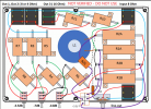
Note that the names I gave to each resistor, eg R3, R4 etc, although they are correct on the diagram and table, aren't in an increasing order from left to right. That's because about half way through the thread, I moved the order of stages but kept the references the same, so eg, the -7dB stage has always been R3 and R4

All versions work in the same attenuation steps, -3.5dB between settings.

Good luck!
 

JohnH

Well-Known Member
Joined
May 31, 2008
Messages
6,149
Reaction score
5,030
Location
Wilton NSW
hi @BlueX

Yes it does look like your build is well optimized for the fan cooling. It's nice to see that the steady-state temperatures with 9V fan and 50W and 100W, give exactly a x2 factor on temp rise (+15C and +30C). So no need to rewrite any text books!.... Its a bit harder to make a similar comparison with the non-fan values, since they are still rising and there are time effects in play.

But I reckon its all good, and its time to play some guitar!
 

rwmarthaler

New Member
Joined
Aug 6, 2023
Messages
6
Reaction score
2
Location
Minnesota
Well, I rewired the switches and same results. However, when I disconnected the coil, I get the attenuation right in line with the stated values but the resistances don’t match up with the 3.5 to 5 ohm range. Instead I get 13.5 - 15.5 ohms. Can only surmise it is the coil but not sure what is going on. I show a resistance of about 0.2 ohms in the coil.

Followed the schematic and checked it against the layout Gene created. Only difference to his is that I added an 8 ohm output.

Will have to dig some more.
 
Last edited:

JohnH

Well-Known Member
Joined
May 31, 2008
Messages
6,149
Reaction score
5,030
Location
Wilton NSW
How about posting some photos of the build? We might spot something. I expect the coil is fine though.

If you put the coil back in, then you could measure resistances across a cord plugged into the 4 ohm output. No speaker no amp, at each setting. They will vary but can be related to what is expected from the diagram.
 

rwmarthaler

New Member
Joined
Aug 6, 2023
Messages
6
Reaction score
2
Location
Minnesota
Success (mostly)! It turns out my 8 ohm jack was wired incorrectly and that was messing up everything else. Will need to fix that but that is a feature I’ll seldom use so it can wait.

Thanks for the tips though! Can’t believe how helpful you have been throughout this forum, John!

I do have a question, however. Playing through the Bassman maxed out through the Les Paul isn’t quite bedroom friendly…. Not unexpectedly though lol! What would the values be for another -7db stage? Or even -14 stage? That will probably come in handy on the 2204 build coming up next.

Thanks!
 

JohnH

Well-Known Member
Joined
May 31, 2008
Messages
6,149
Reaction score
5,030
Location
Wilton NSW
hi @rwmarthaler

Great news, and you are very welcome! What I like best about this project is getting involved to see and talk about all the builds that people do. Its such a buzz to see each one being a success.

If you want some more attenuation, you can just add on extra stages and the values are the same, for the same dB reductions, as stages 2, 3 and 4.

Or in one case, a -28dB stage was added at the end! (three resistors for that one). -28 is the next x2 step after -3.5, -7 and -14. With that, he got every 3.5dB increment from -7dB down to -59.5dB. At that level a 50W amp is sounding like 0.06mW (which apparently could still be heard!)
 
Last edited:

Gene Ballzz

Well-Known Member
Joined
Feb 19, 2013
Messages
4,695
Reaction score
6,513
Location
Las Vegas, NV
Success (mostly)! It turns out my 8 ohm jack was wired incorrectly and that was messing up everything else. Will need to fix that but that is a feature I’ll seldom use so it can wait.

Thanks for the tips though! Can’t believe how helpful you have been throughout this forum, John!

I do have a question, however. Playing through the Bassman maxed out through the Les Paul isn’t quite bedroom friendly…. Not unexpectedly though lol! What would the values be for another -7db stage? Or even -14 stage? That will probably come in handy on the 2204 build coming up next.

Thanks!

It hasn't been asked or mentioned: have you tried combining all of the stages? They don't need to be only used, one at a time.
Just Curious?
Gene
 

rwmarthaler

New Member
Joined
Aug 6, 2023
Messages
6
Reaction score
2
Location
Minnesota
Thanks for the info on the extra stages John! I think one more 14db should do the trick.

Gene, I was able to get everything attenuating as should be, thankfully. Always a cool thing when results match perfectly with the schematic.

I will add some pictures to the completed build thread once I get that added stage wired up.

This thing sounds so amazing! The 5F2 cranked all the way for natural tube fuzz is incredible to hear at bedroom levels. Can't get that sound from a pedal...
 

JohnH

Well-Known Member
Joined
May 31, 2008
Messages
6,149
Reaction score
5,030
Location
Wilton NSW
Thanks for the info on the extra stages John! I think one more 14db should do the trick.

You could use your dB app to judge that before commiting to it, by getting the volume down to the level that you seek in a less toneful way, eg using a pedal or amp or guitar controls, and then measure how many dB's less that is.
 

rwmarthaler

New Member
Joined
Aug 6, 2023
Messages
6
Reaction score
2
Location
Minnesota
You could use your dB app to judge that before commiting to it, by getting the volume down to the level that you seek in a less toneful way, eg using a pedal or amp or guitar controls, and then measure how many dB's less that is.
That’s a real good idea about using a pedal to gauge desired decibel attenuation! I will do that with the trusty Rat.

When adding a stage, I can add it in between any previous stage (2,3, and 4), right? I would just wire the resistors and switch in between, for example, stage 2 and 3 and leave everything else as is?
 

JohnH

Well-Known Member
Joined
May 31, 2008
Messages
6,149
Reaction score
5,030
Location
Wilton NSW
Yes that's right, with M2 and M4 the order of stages, or how many stages there are after stage 1, makes negligible difference.
 

Gingerale08

New Member
Joined
Sep 18, 2023
Messages
12
Reaction score
3
Hi,

New member here, joined when I found this thread! Amazing work, big thanks for putting all this info together. I have been reading and searching the thread but have a couple of questions since I'm pretty new to this. I have built pedals before and assembled kits but am still a bit "paint by numbers" so to speak...

I'm planning to build an M2, 8 ohm version but for 100W. And, I would like to add the "M4 add-on" with -3.5/-7 switching. My use case is that I have different size amps: 85W, 40W and 18W. And I use them for rehearsal/gigs so I need them to be reasonably loud, my experience with a Dr Z attenuator (and others) is that I usually need only slight attenuation when playing with my band (perhaps a bit more for the 85W Mesa...) Hence the -3.5 dB switch.

This will be a "live use" attenuator primarily. I don't really need a "home/bedroom attenuator" as much but will keep the other attenuation stages and the line out since you never know when you need them at some point. So, my build would be a M2 plus the -3.5/-7 dB switch add-on only. My questions:

- For 100W, you just double up the W ratings on all resistors from 50W -> 100W and 25W -> 50W, right? How about the switches? They're ok for 5A/120V?
- The inductor for 100W: I read that I should go for a AWG 16, 0.9 mH, right? I found one seller on eBay where you could select the wire diameter and inductance - the closest I could get from them was wire diameter 1.5mm (which would be about AWG 15 I guess) and inductance 1.0 mH (or 1.2 mm/0.8 mH, or 1.2 mm/1.0). My assumption is that for a 100W version, rather go a bit bigger than the other way around so that should be ok?
- Then, doing the add-on. I tried to add the switch to your M2 layout and followed the layout you did for @Dretot earlier. If I follow your schematic I need to add the resistor R2C and the switch, but want to check if I get the switch wiring and output from the switch right? I made a drawing but not sure if I should post it here in case it's wrong? (I feel like I need a drawing of the components when building, not just a schematic, so your M2 layout on page 112 is perfect for me, but I need to add to it.)

Thankful for any input!
 

Gene Ballzz

Well-Known Member
Joined
Feb 19, 2013
Messages
4,695
Reaction score
6,513
Location
Las Vegas, NV
@Gingerale08
FIRST> :welcome: to the forum!
NEXT> Its OK to post re-draws, experimental drawings, etc, even if in error, as they can easily be edited or swapped for corrected ones! The important part is that if you modify any well proven drawing (especially from @JohnH ) that you clearly identify it as a modification or re-draw of the original! For example, right near or underneath John's tag with date and J Hewitt, you could add the text "Modified by GingeraleO8/ date" as @drdreyer did in post # 3,721 of this thread. This helps keep this lengthy thread semi-organized and avoid errors that could be misconstrued/misunderstood, in the future!

Another way is to initiate private contact with @JohnH, me or other author of a drawing and do your "spitballing" offline, through private email, before posting a drawing here. Unfortunately, the PM/Conversation system of this site does ot readily support the sharing of pdf, jpeg, etc files, through the messages.

It should also be noted that almost any and all of the added "bells & whistles" to the simplest design usually add at least a couple or more db to the overall attenuation level. Something to consider when/if desiring to make this design into a "Swiss Army Knife" type of device!

Just My Thinkin' & Again, Welcome & Thanks,
Gene
 
Last edited:

Gingerale08

New Member
Joined
Sep 18, 2023
Messages
12
Reaction score
3
@Gingerale08
FIRST> :welcome: to the forum!
NEXT> Its OK to post re-draws, experimental drawings, etc, even if in error, as they can easily be edited or swapped for corrected ones! The important part is that if you modify any well proven drawing (especially from @JohnH ) that you clearly identify it as a modification or re-draw of the original! For example, right near or underneath John's tag with date and J Hewitt, you could add the text "Modified by GingeraleO8/ date" as @drdreyer did in post # 3,721 of this thread. This helps keep this lengthy thread semi-organized and avoid errors that could be misconstrued/misunderstood, in the future!

Another way is to initiate private contact with @JohnH, me or other author of a drawing and do your "spitballing" offline, through private email, before posting a drawing here. Unfortunately, the PM/Conversation system of this site does ot readily support the sharing of pdf, jpeg, etc files, through the messages.

It should also be noted that almost any and all of the added "bells & whistles" to the simplest design usually add at least a couple or more db to the overall attenuation level. Something to consider when/if desiring to make this design into a "Swiss Army Knife" type of device!

Just My Thinkin' & Again, Welcome & Thanks,
Gene
Hi and thanks, that's very helpful!

I didn't want to clog up the thread with bad drawings but I'll give it a shot! I think my options as a new user are a bit limited so it is easiest to post the drawing, if it's incorrect I'll remove it.

So this is based on the drawing by @JohnH on page 112, post #2223 and modified by me with an attempt to add the -3.5/-7 dB switch from M4 only. So there's the R2C resistor added (not where it will be placed in reality though :)) and the switch, a bit crudely drawn but I think you get the picture.

Does it look right?
 

Attachments

  • m2-addon-forumpost.png
    m2-addon-forumpost.png
    609.2 KB · Views: 34

JohnH

Well-Known Member
Joined
May 31, 2008
Messages
6,149
Reaction score
5,030
Location
Wilton NSW
Hi and thanks, that's very helpful!

I didn't want to clog up the thread with bad drawings but I'll give it a shot! I think my options as a new user are a bit limited so it is easiest to post the drawing, if it's incorrect I'll remove it.

So this is based on the drawing by @JohnH on page 112, post #2223 and modified by me with an attempt to add the -3.5/-7 dB switch from M4 only. So there's the R2C resistor added (not where it will be placed in reality though :)) and the switch, a bit crudely drawn but I think you get the picture.

Does it look right?
Thanks for your interest. I'll take a look at the diagram, and yes it should be a good starting point since it has most of what uou need, including the two R1 parts.

Once the wiring is confirmed, you'll need to allow that all your parts will be bigger, and you'll need a fan, and R2C will need a place where it can be bolted to the chassis. So a bigger case is needed. Plus on M4, stage 1 has three parts, as a result of the -3.5dB setting that you need

For the switches, given that it's for 100W, and also more power may get past stage 1, id recommend an 8 or 10Amp rating. I'll look at the coil....

Are you going to have the outputs for different ohms? or just the 8 ohm outs?
 

Gingerale08

New Member
Joined
Sep 18, 2023
Messages
12
Reaction score
3
Thanks for your interest. I'll take a look at the diagram, and yes it should be a good starting point since it has most of what uou need, including the two R1 parts.

Once the wiring is confirmed, you'll need to allow that all your parts will be bigger, and you'll need a fan, and R2C will need a place where it can be bolted to the chassis. So a bigger case is needed. Plus on M4, stage 1 has three parts, as a result of the -3.5dB setting that you need

For the switches, given that it's for 100W, and also more power may get past stage 1, id recommend an 8 or 10Amp rating. I'll look at the coil....

Are you going to have the outputs for different ohms? or just the 8 ohm outs?
Thanks for checking it out! Yes, I have planned to put a 12V fan in it. And when looking up parts specs I realized that resistors rated for 100W are huge! So I figure I need a 12"x8" enclosure at the very least. Perhaps even bigger, I'll see what I can find.

My main need is for 8 ohm output only, although 4 could be handy sometimes. I don't think I'll ever need a 16 ohm output though.

Great to know about the switches, I'll look up higher rated ones.
 

JohnH

Well-Known Member
Joined
May 31, 2008
Messages
6,149
Reaction score
5,030
Location
Wilton NSW
hi @Gingerale08
Thinking more on your build, it might be good to see how it lays out if its made all out of 50W rated resistors. I'd like to try that myself and I'll post a diagram in a few days.

The ratings needed for a 50W M4 have a few where the ratings go up compared to M2 from 25W to 50W, (see M4 diagram) so for a 100W build, they would be two in a pair, and the 25W ones go up to 50W. But also, where in M2, R1 is 100W in the base design, in M4 it splits into two at 50W, so for a 100W build, each of those becomes two.

Using all the same size should allow a nice consistent layout and good spread of heat.
 

Gene Ballzz

Well-Known Member
Joined
Feb 19, 2013
Messages
4,695
Reaction score
6,513
Location
Las Vegas, NV
Yeah, those name brand (ARCOL, TE, etc.) resistors in 100 watt are HUGE and rather tedious for layout. Splitting each 100 watt into two 50 watt pieces makes a lot of sense! That's one of the main reasons I use the ones from chinesiawanoreanam. All that may change though, as global tensions escalate!
Just Noticin'
Gene
 

Gingerale08

New Member
Joined
Sep 18, 2023
Messages
12
Reaction score
3
hi @Gingerale08
Thinking more on your build, it might be good to see how it lays out if its made all out of 50W rated resistors. I'd like to try that myself and I'll post a diagram in a few days.

The ratings needed for a 50W M4 have a few where the ratings go up compared to M2 from 25W to 50W, (see M4 diagram) so for a 100W build, they would be two in a pair, and the 25W ones go up to 50W. But also, where in M2, R1 is 100W in the base design, in M4 it splits into two at 50W, so for a 100W build, each of those becomes two.

Using all the same size should allow a nice consistent layout and good spread of heat.
Great, thanks! I'll look forward to what you come up with. I started with the M2 diagram since there was a layout/drawing available for that one, but it makes sense to make a "stripped-down M4" (only -3.5/-7 switch) instead of adding to the M2 version.
 

Gingerale08

New Member
Joined
Sep 18, 2023
Messages
12
Reaction score
3
Yeah, those name brand (ARCOL, TE, etc.) resistors in 100 watt are HUGE and rather tedious for layout. Splitting each 100 watt into two 50 watt pieces makes a lot of sense! That's one of the main reasons I use the ones from chinesiawanoreanam. All that may change though, as global tensions escalate!
Just Noticin'
Gene
Where do you buy parts from? I'm in Europe so it's a bit difficult to find parts for a reasonable price. So far I have been looking at Mouser, they at least have everything available.
 
Top