Hello all from down under once again... I have a Vox amp and only posted here once before. Been informed this is as good a forum as any other for Vox stuff?
I have been battling with, what I thought would be a simple issue, for some time.
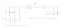
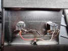
I have built a Vox VFS2A footswitch. For those unfamiliar with these, it is a simple two button foot switch with LEDs. One turns reverb on and off, the other tremlo.
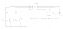
Tremolo works fine with LED and all. However the Reverb will only work if I disconect the negative of the LED. I am using a switched stereo jack and a sp footswitch. The amp supplies voltage to the output of the foot switch. It is around 16V. The tremolo works because when you plug the footswitch in, it is in the open state. So the ground and signal are not making contact. So when switched, they make contact and I just connect the LED through a resistor to the same points.
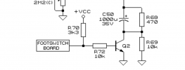
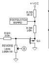
The REVERB when you first plug in, is in a closed state. So the signal and ground are making contact and when I switch to open the contacts the reverb works fine. UNTILL I connect the LED. The led is connected to the signal of the reverb and the sheild. Reverb does not work, but led does. Disconnect the Shield and the Reverb works, but the LED doesn't?? I know I can do this with a battery. But I know this is NOT how vox do it. All the diagrams and schematics for the vox footswitch do NOT work properly. All links I find to the schematic do not work.
I have been trying for a while to find a way of separating the sheild into two so the one that goes to the reverb LED is not connected to any other sheild.
Any guidance would be gratefully appreciated. I have invested so much time and money in this, that I would have been far better off just buying a new vox footswitch to start with.
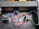
The first image is what I started with. The 2nd is where I am at now.
I have been battling with, what I thought would be a simple issue, for some time.
I have built a Vox VFS2A footswitch. For those unfamiliar with these, it is a simple two button foot switch with LEDs. One turns reverb on and off, the other tremlo.
Tremolo works fine with LED and all. However the Reverb will only work if I disconect the negative of the LED. I am using a switched stereo jack and a sp footswitch. The amp supplies voltage to the output of the foot switch. It is around 16V. The tremolo works because when you plug the footswitch in, it is in the open state. So the ground and signal are not making contact. So when switched, they make contact and I just connect the LED through a resistor to the same points.
The REVERB when you first plug in, is in a closed state. So the signal and ground are making contact and when I switch to open the contacts the reverb works fine. UNTILL I connect the LED. The led is connected to the signal of the reverb and the sheild. Reverb does not work, but led does. Disconnect the Shield and the Reverb works, but the LED doesn't?? I know I can do this with a battery. But I know this is NOT how vox do it. All the diagrams and schematics for the vox footswitch do NOT work properly. All links I find to the schematic do not work.
I have been trying for a while to find a way of separating the sheild into two so the one that goes to the reverb LED is not connected to any other sheild.
Any guidance would be gratefully appreciated. I have invested so much time and money in this, that I would have been far better off just buying a new vox footswitch to start with.
The first image is what I started with. The 2nd is where I am at now.

")
")