1972 Plexi-Crazy Bias numbers help

  • Thread starter mmanthony
  • Start date
  • This site may earn a commission from merchant affiliate links like Ebay, Amazon, and others.

mmanthony

New Member
Joined
Aug 13, 2024
Messages
7
Reaction score
0
Hi folks,
I have an old 72 plexi that was fortunate enough to Inherit. At first it made no sound. I've built a bunch of amps years ago and took a look and checked some voltages. I noticed that one of the one of the 1k/5W resistors attached to pin4 of one of the output sockets had a broken lead so I replaced it. On it went and it sounds amazing:)
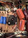
It's been modded for more gain many years ago it seeks with a master volume, some additional bypass caps in the preamp and some additional caps in the power section but most of the meat of the signal chain seems original (caps, resistors, solder joints).

Again, it sounds bad ass....BUT, I decided to check the bias as one would and it seems insanely high. I used my old Weber BiasRite checker and I got 388 volts-ish on the plates (they were not matched and are the original Tesla Tubes so that may have something to do with it or some out of range resistor... Also I know this seems quite low but I thought it may have something to do with the mods and running on lower voltages as a kind of fake Variac???

Either way, the Cathode current on the meter read 95!! From the bias equation I believe they should be around 45..
Again, it sounds incredible, but I fear that it may only sound that way for 3 minutes before it blows something...

I know a bit about amps and have built my own plexi and a few other amps but I don't know that much. Wondering if anyone has any ideas. It could be the bias resistor needs to be replaced, or maybe the tubes (or both).
Also, This is the lowest I could get the reading on the bias pot!

Am I reading something wrong?

Thank you for any help or insight!

-Matt
 

This site may earn a commission from merchant links like Ebay, Amazon, and others.

mAx___

Well-Known Member
Joined
Apr 3, 2012
Messages
770
Reaction score
660
Remove the power tubes and make sure that you get negative DC voltage on pin 5 of each power tube. Don't know your amp specifically but it should read around -30/-50V.
 

neikeel

Well-Known Member
Joined
Feb 12, 2014
Messages
8,449
Reaction score
9,597
First it has been modded so we don’t know what has been done to the power section (anti fly back diodes, bias resistors, grid stoppers etc).
Please post pics. and, yes confirm negative voltage on pin 5 of each octal.
Pending those that is extraordinarily hot (if at idle with no input signal) and may explain low anode voltage (inverse relationship between that and bias current).
You can get it lower for experimentation croc clipping a resistor over the bias resistor (the one that goes parallel with caps to bias ground bus) but we need to know what is there now.
 

2L man

Well-Known Member
Joined
Sep 30, 2020
Messages
401
Reaction score
281
If bias current is both tube combined current it is not too high. If each tube cathode currents are 95mA then adjust each to about 50mA.
 

neikeel

Well-Known Member
Joined
Feb 12, 2014
Messages
8,449
Reaction score
9,597
Depends on anode voltage:
17.5/420v = 42mA is 70% at idle so 50 = v hot
At other extreme
17.5/360 = 47mA so 50 is still hot.
At correct current draw you will probably be somewhere in the middle
 

mmanthony

New Member
Joined
Aug 13, 2024
Messages
7
Reaction score
0
Hi Max,
Thank you for your reply. I'm back from vacation and was able to check the voltages on pin 5. I'm getting around -23 volts. The grid resistor is typically 5.6k here but this amp has been modded to use 3.3k here. Not sure if that makes a difference. I'm assuming it would.
 

mmanthony

New Member
Joined
Aug 13, 2024
Messages
7
Reaction score
0
If bias current is both tube combined current it is not too high. If each tube cathode currents are 95mA then adjust each to about 50mA.
If I just measure the voltage on pin 5 I get -23 volts. Pin 3 plate voltage is 374V
 

mmanthony

New Member
Joined
Aug 13, 2024
Messages
7
Reaction score
0
Thanks everyone. I will post some pics now. Also of note is that it has a master volume mod.
 

mmanthony

New Member
Joined
Aug 13, 2024
Messages
7
Reaction score
0
Here are a few photos in case any are helpful:
 

Attachments

  • IMG_1252.jpg
    IMG_1252.jpg
    842.2 KB · Views: 21
  • IMG_1257.jpg
    IMG_1257.jpg
    682.8 KB · Views: 20
  • IMG_1253.jpg
    IMG_1253.jpg
    822.8 KB · Views: 20
  • IMG_1254.jpg
    IMG_1254.jpg
    858.4 KB · Views: 53
Last edited:

mAx___

Well-Known Member
Joined
Apr 3, 2012
Messages
770
Reaction score
660
Hi Max,
Thank you for your reply. I'm back from vacation and was able to check the voltages on pin 5. I'm getting around -23 volts. The grid resistor is typically 5.6k here but this amp has been modded to use 3.3k here. Not sure if that makes a difference. I'm assuming it would.
Hi! Welcome back. I think that's not enough negative voltage to have a good idle bias current range. Check if the resistors in that circuit are in spec or if they drifted and need to be replaced. Also it would be a good idea to replace the bias caps as they look original and thus are 50+ years old.
One of the 1K 5W screen resistors seems to have burnt marks on one end. It could be open, check it out.
I don't know this circuit good enough but it has some not so good looking work from what I can see. I hope the experts chime in and give you other suggestions.
 

mmanthony

New Member
Joined
Aug 13, 2024
Messages
7
Reaction score
0
Thanks Max.
I'll check the resistor values and look at replacing the 10uf 60v electrolytic
 

PelliX

Well-Known Member
Joined
Jun 16, 2020
Messages
7,149
Reaction score
14,559
I hope they are rated 160V and not 60V

img_1254-jpg.156028


Yup, they are. But some of that solderwork around the rectifier and that capacitor leg dangling around the board mounting post give me the eebie jeebies...
 

neikeel

Well-Known Member
Joined
Feb 12, 2014
Messages
8,449
Reaction score
9,597
I typically use 200v bias caps - as much for physical size (F&Ts are good).
-23v on grids can be quite hot, -35 (+/- 10v is a good place to start) although ultimately current draw will be more specific to the tubes you are running.
Early JMP50s did not have screen resistors. I have talked people through the correct way to install them before. I use 1k 3w Welwyns (the green barrel shaped ones) mounted on the sockets between pins 4 and 6 and you will need to add a yellow link wire between pins 6 and a yellow feed wire from the screens turret (the one where the restore are tacked too now to pin 4 of v4.
Ditch those snubbers (the 4 orange drop type caps) and take that white wire off the bias feed (short one to the rectifier) and take a longer wire and solder it to the bias feed resistor (where you removed other wire) and re-route to solder it to one of the permanently ’hot’ ht ac feeds from the power transformer so that the bias circuit gets voltage when the amp is on standby (ie as soon as mains is on). That way your output tubes live longer and less chance of losing your PT.
 

neikeel

Well-Known Member
Joined
Feb 12, 2014
Messages
8,449
Reaction score
9,597
The grid resistor is typically 5.6k here but this amp has been modded to use 3.3k here. Not sure if that makes a difference. I'm assuming it would.
Grid resistors are also non-stock but can be useful in a modded for gain amp to stop oscillation or just ameliorate dodgy wiring layout.
3k3 vs 5k6 makes no difference.
 

Pete Farrington

Well-Known Member
Joined
Jan 18, 2021
Messages
3,216
Reaction score
4,245
Location
Staffordshire UK
-23v on grids can be quite hot, -35 (+/- 10v is a good place to start) although ultimately current draw will be more specific to the tubes you are running.
The magnitude of the voltage measured at pin5 will be less than the true level, because the input resistance of the meter causes voltage to be dropped across the 220k grid leak.
Most meters are 10M input resistance, some only 1M. The lower the meter's input resistance, the more the reading will get skewed.

It's the same scenario as trying to measure the voltage at LTP grids; the meter's internal input resistance creates a false reading, and by pulling the grid voltage down towards circuit common, affects the circuit operating point.

Assuming that the grid leak and grid stopper resistors are good, the better measurement point for the actual bias voltage being applied to the control grids is at the node at the output of the bias supply, that feeds the grid leak resistors.
 

mmanthony

New Member
Joined
Aug 13, 2024
Messages
7
Reaction score
0
Thanks for all this help everyone. I agree some of the previous mods don't look great from a solder perspective,
I'm feeling like I should clean up this section a bit and replace those capacitors.

Ultimately I'm going to sell the amp so I'm trying to decide if I should just fix this section up and leave the high gain mods throughout the amp or if it makes more sense to return it to spec across the board...
 
Last edited:

PelliX

Well-Known Member
Joined
Jun 16, 2020
Messages
7,149
Reaction score
14,559
Ultimately I'm going to sell the amp so I'm trying to decide if I should just fix this section up and leave the high gain mods throughout the amp or if it makes more sense to return it to spec across the board...

Given the amount of bodging in there just on the pics you posted, returning to a neat, stock setup might be pretty labor intensive. I'd fix up the safety and reliability issues, make sure it sounds good and try to sell it in that condition. Once someone has put a drill to the chassis, it kills the value from a collector's point of view a bit, so I'd sell it more as a "player's amp". Just my opinion, of course.
 

Latest posts


Top